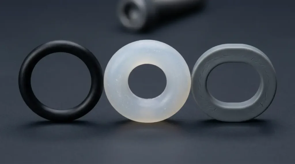
After-sales service records for industrial equipment show the same three complaints year after year: fluid leaks, gas leaks, and cracked seal rings. A new batch of rings goes in, and three months later the unit leaks again. In most cases, the root cause is not the ring itself. The real issue is that no one knows why it leaked in the first place. That puts equipment makers in the worst position. The rings come from the supplier, the structure comes from the design engineer, and the operating conditions come from the end user. Once leakage happens, all three sides start passing the blame, and no one can clearly identify which step failed.
Seal ring failure analysis already has a mature classification system. Mainstream sealing manufacturers publish similar failure-analysis guides, including Marco, GMORS, and Canyon. Most problems fall into 12 causes. These 12 cover nearly every ring now leaking oil, leaking gas, or cracking in service.
This article breaks them down into three groups: oil leakage (2 causes), gas leakage (5 causes), and cracking (5 causes). After reading it, you can make an initial judgment on whether the failed ring is a material-selection issue, a design issue, or a manufacturing issue—and what to discuss with the supplier next.
Three material codes appear repeatedly below. VMQ is the most common general-purpose silicone. MVQ is the UV-resistant modified grade for outdoor use. FVMQ is fluorosilicone for oil resistance.
Oil Leakage: The Medium Has Damaged the Ring (2 Causes)
Oil leaks often look the same from the outside—oil residue around the ring. Once disassembled, the root cause is usually wrong material selection. In a smaller number of cases, the chemical medium has attacked the ring. Silicone is not the default choice for oil resistance. Using it in the wrong service is the main issue in this category.
1. Wrong Elastomer Choice — VMQ Is Not Resistant to Mineral Oil (Oil Leakage)
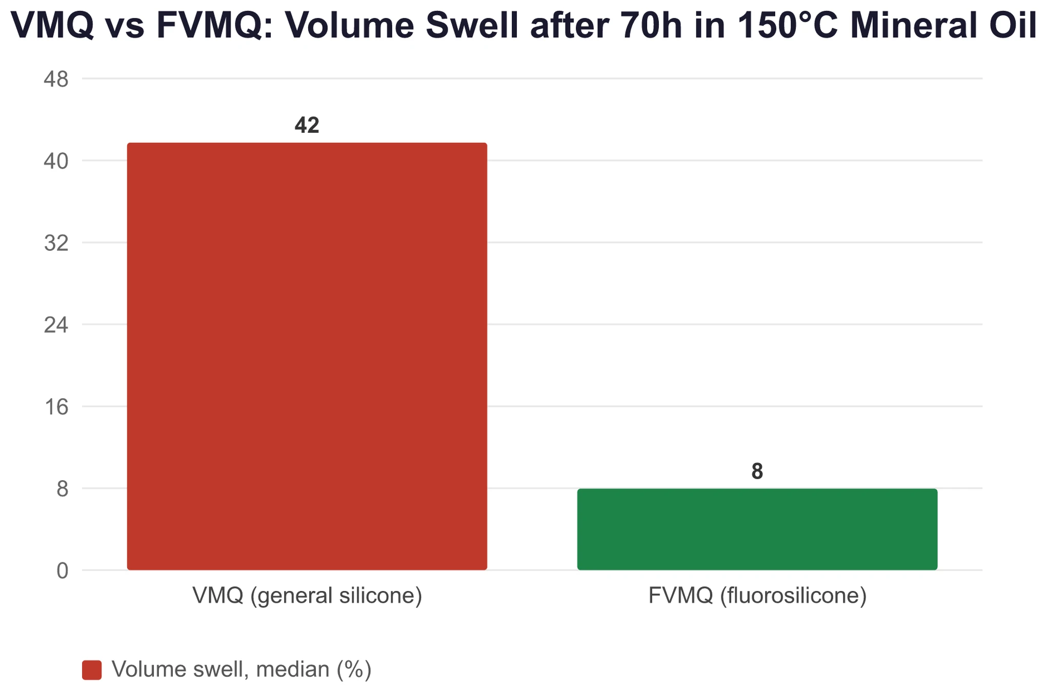
The first and most commonly overlooked cause of oil leakage is choosing the wrong elastomer. Standard silicone rubber (VMQ) has poor resistance to mineral oil. That is clearly stated in ASTM D2000, the rubber classification standard for oil resistance. Under ASTM D471 liquid-immersion testing, VMQ soaked in mineral oil at 150°C for 70 hours shows a volume swell of 25% to 60%. In aromatic reference oil IRM 903, swelling can reach 40% to 100%. The ring swells, softens, and loses modulus. Sealing stress drops, and oil starts to leak past the seal.
For oil service, the usual replacement is NBR (nitrile rubber) or FKM (fluoroelastomer). Both are rubber materials, and like silicone they are typically molded and vulcanized, so the processing route is similar. Where both oil resistance and heat resistance are required, FVMQ fluorosilicone is the better fit. Its swell is only 1% to 15%. Oil-resistant seals are not always the core strength of a Silicone Product Manufacturer, but the material recommendation should still be stated plainly. Forcing VMQ into oil service creates a failure risk from the start.
2. Chemical Degradation — Acids and Alkalis Hydrolyze the Backbone (Oil Leakage)
Strong acids (pH below 3), strong alkalis (pH above 9), strong oxidizers, and polar solvents such as ketones and esters will chemically degrade silicone rings during long-term exposure. Typical signs include surface blistering, cracks, tackiness, and powdering. On the shop floor, people often describe this as peeling or shedding debris. Silicone handles weak acids, weak alkalis, and water reasonably well. Once the pH crosses 3 or 9, or when exposed to high-temperature, high-pressure steam above 150°C, the siloxane backbone (Si-O-Si) can hydrolyze and break down.
This failure mode does not spare one silicone grade over another. VMQ, MVQ, and FVMQ can all fail the same way. Against aggressive chemical media, silicone is simply not robust enough. The quick check is a visual inspection after removal. If the surface is flaking, friable, or turns to powder under a fingernail, this is the likely cause.
Gas Leakage: The Sealing Force Is Gone (5 Causes)
Gas leakage is harder to diagnose than oil leakage. Oil leaves visible traces. Gas does not. When a pressure-hold test fails, an IP67 enclosure slowly loses tightness, or a vacuum chamber cannot hold vacuum, the cause usually falls into one of these five categories. The first three involve poor compression or physical damage. The fourth is a basic material limitation. The fifth appears only in high-pressure gas service.
3. Compression Set — The Primary Cause of Gas Leakage (Gas Leakage)
The main cause of gas leakage is compression set, or CS. Under long-term compression and heat inside the gland, the crosslinked network gradually relaxes and rebound keeps falling. After removal, the cross-section that started round now looks rectangular. In factory terms, the ring has taken a set and won’t spring back.
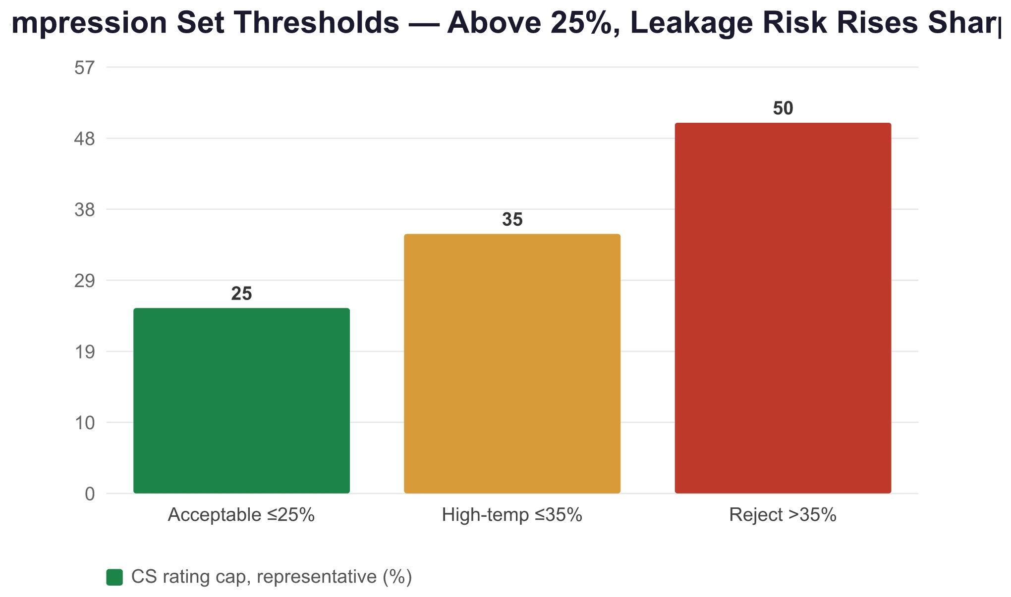
Under ISO 815-1 compression-set testing, silicone rings compressed at 150°C for 22 hours typically show permanent deformation in the range of 9% to 25%. Above 25%, the part is generally considered nonconforming. For high-temperature service, many applications use a limit of 35% or less. CS is the first screening metric for deciding whether a seal is still fit for service. Before changing the ring, confirm the actual operating temperature. If the application often runs above 150°C, standard VMQ is already near its limit and a heat-resistant formulation is needed.
4. Wrong Gland Design — Compression Ratio Never Reaches 15% to 25% (Gas Leakage)
Many gas leaks are not caused by the ring at all. The real problem is poor gland design, and this is one of the most overlooked issues. ISO 3601-2, the O-ring gland design standard, states the requirements clearly: static sealing compression should be 15% to 25%, dynamic sealing 10% to 15%, gland fill 60% to 85% and not above 90%, stretch 0% to 3% and not above 5%, and gland surface roughness Ra 0.4 to 0.8 μm.
If compression is below 15%, sealing force is too low and leakage is expected. If compression goes too far, above 30%, the ring gets over-compressed, loses recovery, and may even crack around the circumference. In the field this is often called over-compression cracking. Gland dimensions are a machine-side design issue. Changing the ring alone will not fix it. This is the kind of problem that must be controlled at the drawing stage because corrective action later is expensive.
5. Extrusion Nibbling — Large Gap Plus High Pressure Tears Out the Edge (Gas Leakage)
When pressure rises and the sealing gap is too large, the ring gets forced into the clearance and a piece is torn away. Common shop terms include edge nibbling, gap extrusion, and missing material at the edge. GMORS gives a practical threshold: the sealing clearance should stay below 0.15 mm. In higher-pressure service, hardness should move up to 80 Shore A, or a PTFE backup ring should be added.
Silicone is soft by nature. Instrument seals often use 50 to 70 Shore A, which is well below 80. That makes this failure mode especially severe for silicone rings. After removal, the low-pressure side often shows jagged notches and material loss along the edge. Prevention comes down to two options: reduce the hardware gap to below 0.15 mm or switch to a higher-hardness compound with a backup ring.
6. High Gas Permeability of Silicone — An Inherent Limitation, Not a Defect (Gas Leakage)
Silicone has one basic material weakness: among elastomers, it is one of the most gas-permeable. Oxygen, nitrogen, carbon dioxide, and water vapor pass through silicone far faster than through NBR or FKM—often by an order of magnitude. In routine IP67 water-resistance applications, this is usually not a problem because water molecules are much less likely to pass through in the same way. But if a silicone ring is used to seal a vacuum chamber, high-pressure gas system, or long-term pressure-hold application, gas will gradually permeate through the material.
This does not mean the ring is damaged. It means the material behaves as expected. The right way to judge this is by application context. A gas leak in a standard atmospheric enclosure is rarely caused by permeability. An unexplained pressure drop in vacuum or high-pressure gas service should point to this cause early in the troubleshooting process. The only real fixes are changing the material—FKM is roughly one order of magnitude lower in permeability—or using a multiple-seal structure.
7. Explosive Decompression — Rapid Depressurization Blisters the Ring from the Inside (Gas Leakage)
If the equipment runs in high-pressure gas service—such as pneumatic systems, diving equipment, or oil and gas exploration instruments—another hidden failure mode must be considered: explosive decompression. Gas dissolves into the ring under long-term high pressure. When the system is depressurized too quickly, the trapped gas expands inside the elastomer and causes internal blisters, tearing, and peeling. Marco lists this as a dedicated failure category in its guide. Because silicone has relatively low tear strength, it is more vulnerable than harder FKM compounds.
This does not occur in normal atmospheric IP67 service. It appears only when high-pressure gas is released rapidly. Most equipment manufacturers will never encounter it. Prevention is straightforward: reduce the depressurization rate and use a harder elastomer.
Cracking: The Ring Structure Has Failed (5 Causes)
A cracked ring is the most visible failure mode and also one of the hardest to judge correctly. The ring may have hardened and become brittle from heat. It may have been cut during assembly. It may have twisted in dynamic service. It may have worn out. Or it may have left the factory under-cured. These five crack patterns point to different failures in different steps of the process.
8. Heat-Aging Hardening — “Burned” Rings with Radial Cracks (Cracking)
The most common cracking cause is heat aging. Long-term overtemperature exposure hardens and embrittles silicone, and radial surface cracks appear. In production settings, this is often called a burned ring or carbonized ring. VMQ silicone is rated for continuous service at 200°C and intermittent service at 230°C. That is its upper limit. The temperature ranges tell the story: at 150°C to 200°C, the surface hardens with minor weight loss; at 200°C to 250°C, the backbone starts to break and elasticity drops; above 300°C, the material powders out.
On a sealing surface that runs continuously at 180°C to 200°C, the condition may appear to stay within spec. But heat aging is cumulative. After six months or a year, cracking can still occur. Accelerated verification by ASTM D573 hot-air aging can catch the issue early. Another option is to move directly to a more heat-resistant elastomer, such as FKM or HNBR.
9. Low Tear Strength — Assembly Damage Is Silicone’s Weak Point (Cracking)
If a silicone ring cracks during installation, this is one of the most common complaints against the material. Silicone tear strength is only 10 to 30 kN/m under ASTM D624 testing. That is roughly half the level of NBR, which typically runs 25 to 50 kN/m. During assembly, if the ring passes over sharp edges, threads, or grooves without proper chamfering, NBR may survive being forced into place. Silicone may split on contact.
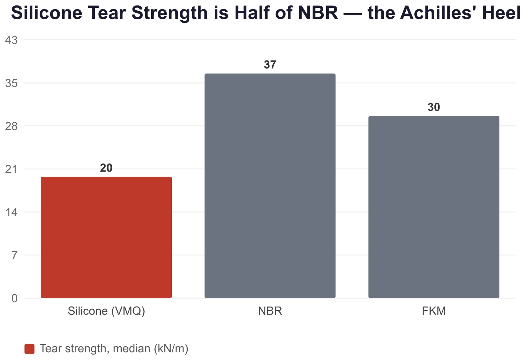
The installed ring may look acceptable at first, but a small nick becomes the starting point for crack growth. Failure later is only a matter of time. This is a built-in material limitation of silicone, not a molding issue. Prevention depends on the assembly side: proper chamfers, edge deburring, lubrication, and controlled stretch below 5%.
10. Spiral Failure — Twisting in Dynamic Seals (Cracking)
Dynamic sealing can produce another crack pattern known as spiral failure. As the ring rolls back and forth in the gland, it twists and develops helical cuts around the circumference. Marco lists the typical triggers: low reciprocating speed, overly soft compound, gland width that is too large, poor surface finish, insufficient lubrication, and an excessive mold parting line on the product surface.
Because silicone is already soft, usually 50 to 70 Shore A, this failure mode needs special attention in reciprocating dynamic seals. Prevention depends on higher hardness, internally lubricated formulations, and proper gland surface polishing. If the application uses reciprocating dynamic sealing, silicone is typically not the first choice. Static sealing is where it performs best.
11. Wear — In Dynamic Sealing, Silicone Wears 4 to 10 Times Faster Than NBR (Cracking)
Silicone rings fail quickly in dynamic sealing because of wear. In Akron abrasion testing, silicone shows 0.5 to 2.0 cm³/1.61 km of wear loss, while NBR shows only 0.1 to 0.5. That is a difference of 4 to 10 times. As a result, the industry default is to use silicone in static seals. In reciprocating dynamic service, its life is often only a fraction of NBR.
When a customer uses a silicone ring in a high-frequency reciprocating seal—such as a pneumatic piston, peristaltic pump, or valve core—and it leaks after three months, the issue is usually not poor ring quality. It is the wrong application for the material. The fix is direct: switch to NBR or FKM and keep silicone in static sealing duty. This is standard industry understanding, and technical literature consistently states that silicone has poor abrasion resistance. That is why it is used mainly in static sealing.
12. Undercure or Manufacturing Defects — Incomplete Vulcanization Causes Tackiness and Extreme Compression Set (Cracking/Leakage)
The last cause is harder to spot: manufacturing defects. If a silicone ring is not fully vulcanized—the shop-floor term is under-cured”—the crosslink density is too low. The ring surface becomes tacky, the compression set can double, and tensile strength can drop by 30% to 50%. A ring like this may leak immediately after installation or fail quickly in service because CS goes out of control.
For compression molding, the process window is tight: VMQ at 170°C ±2°C, cavity pressure of 10 to 15 MPa, and cure time reaching T90 plus an additional 1 to 3 minutes. T90 is the point on the cure curve where 90% crosslinking is reached. Miss any one of these controls and the risk rises. This is a key checkpoint for the molding factory, and it is also a valid supplier-audit question for buyers: how is the cure curve controlled? During sampling, ask the supplier to provide a cure-curve report based on ASTM D5289 moving-die rheometer testing. It is an effective screen before mass production.
How to Use This Checklist: Trace the Cause Back from the Symptom
These 12 causes are the starting point for troubleshooting, not the final judgment. Once a failed ring is removed, working backward from the visible symptom is the fastest approach.
| Symptom | First Check | Most Likely Cause | Parameter Threshold |
|---|---|---|---|
| Oil residue outside the ring, tacky surface | Elastomer type + medium | C1 Wrong elastomer choice / C2 Chemical degradation | VMQ mineral oil swells +25% to +60% |
| Pressure-hold loss, IP67 gas seepage | Cross-section shape + clearance | C3 Compression set / C4 Wrong gland design / C5 Nibbling | CS ≤25%, clearance <0.15 mm |
| Vacuum or high pressure will not hold | Application context | C6 High permeability / C7 Explosive decompression | Occurs only in high-pressure gas service |
| Radial cracks on the surface | Temperature history | C8 Heat-aged ring | Continuous service ≤200°C |
| Cracks at the assembly position | Assembly path | C9 Cut during assembly / C10 Spiral twist | Sharp edges, excessive stretch |
| Rapid failure in dynamic sealing | Operating condition | C11 Wear | Silicone wear is 4 to 10 times that of NBR |
| New ring is already tacky and leaking | As-delivered condition | C12 Undercure | T90 cure-curve control |
The troubleshooting flow has three steps: first classify the symptom as oil leakage, gas leakage, or cracking; then use the parameter thresholds to narrow it down to one or two likely causes; finally compare with the operating conditions to decide whether the error came from material selection, design, or manufacturing.
Common Questions
How long does a Silicone Seal Ring usually last?
Service life depends on operating conditions. In static service at room temperature, 5 to 10 years is common. In dynamic service above 80°C, 1 to 3 years is more typical. In oil-containing environments, life may drop to weeks or months. It is normal for the same ring to last many times longer in one machine than in another.
A silicone ring hardened outdoors in less than two years. Is that ozone cracking?
No. Ozone resistance is one of silicone’s strengths. Ozone cracking is a typical failure mode for NBR and CR, not for silicone. The real cause of outdoor hardening is typically that standard VMQ has poor UV resistance. The fix is to switch to MVQ, a methyl-vinyl UV-resistant modified silicone, or add UV stabilizers.
Does a leaking silicone ring mean poor quality?
Not necessarily. First rule out three other categories: design issues such as incorrect gland compression, operating-condition issues such as gas permeation in high-pressure service, and assembly issues such as cutting the ring on a sharp edge. Only then should the ring itself be judged. Blaming the supplier at the first sign of leakage does not prevent the same failure from happening again.
These 12 causes are the starting point for troubleshooting, not the final ruling. The next time equipment leaks fluid or gas, first classify the symptom—oil leakage, gas leakage, or cracking. Then determine whether the failure came from material selection, design, or manufacturing. If the cause is unclear, send the supplier the operating parameters, including medium, temperature, pressure, and whether the seal is static or dynamic, and ask for their assessment. That is also a good way to judge supplier competence. A supplier that can discuss these 12 failure modes in technical terms is far more reliable than one that only quotes price.