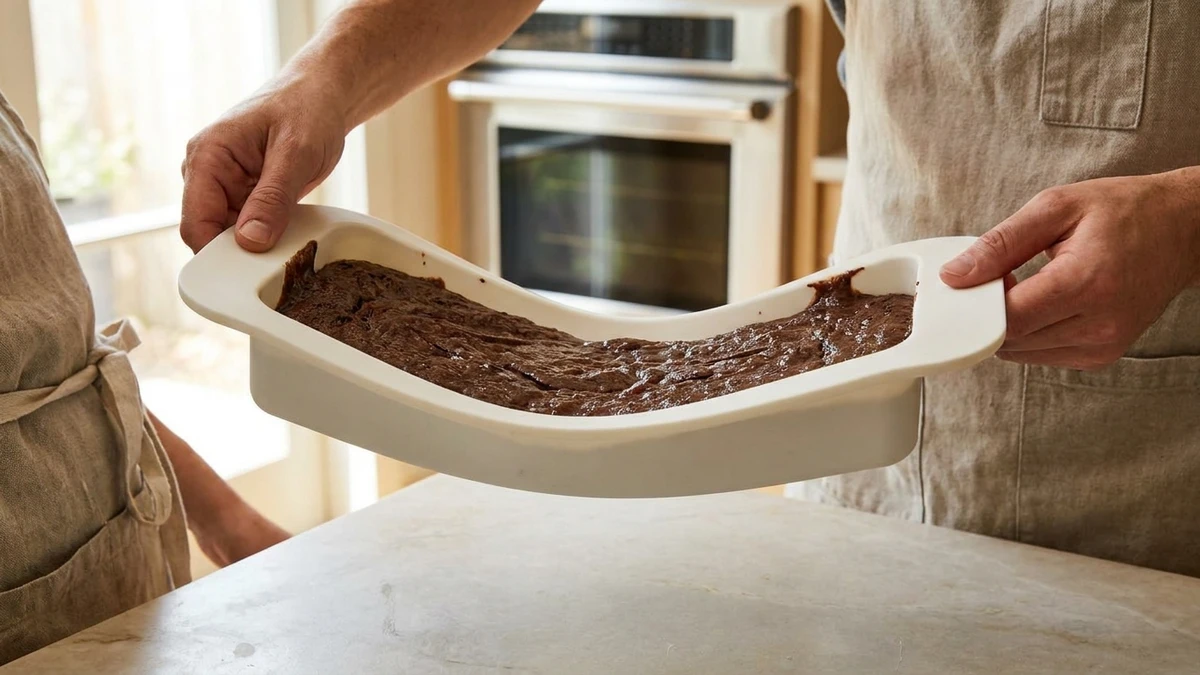
When a silicone baking pan is full of batter, structural failures rarely happen during baking. They happen during the short walk from the counter to the oven. You grip both ends, the center sags, and batter spills over the lowest edge. Australian consumer reviews and manufacturer user guides consistently emphasize one key tip: always support a filled silicone pan with a rigid baking sheet during transfer.
This issue does not mean the silicone pan is defective. It also does not mean you can fix it simply by making the material harder. If you are developing a new silicone pan, you must answer four practical questions first: How full is it? What is the unsupported span? What supports the base? Will users carry it by the rim with two hands? The rim, base, and external trays each address a different part of the load path. You must validate the final concept with fully loaded physical samples.
Evaluate Sagging and Instability Under Real-World Operating Conditions
Static sagging and carrying instability both stem from flexible silicone deforming under load. However, they represent entirely different boundary conditions.
A continuous countertop supports the entire base. Do not confuse this with an unsupported span. Static mid-span sagging happens when a pan rests on two narrow oven rack wires. Manual carrying is far more demanding. The user lifts the loaded weight from two end grip points, turning the middle section into a suspended span. The liquid batter shifts toward the lowest sag point. The diagram below illustrates these two load paths, rather than a specific deflection value for a single size.
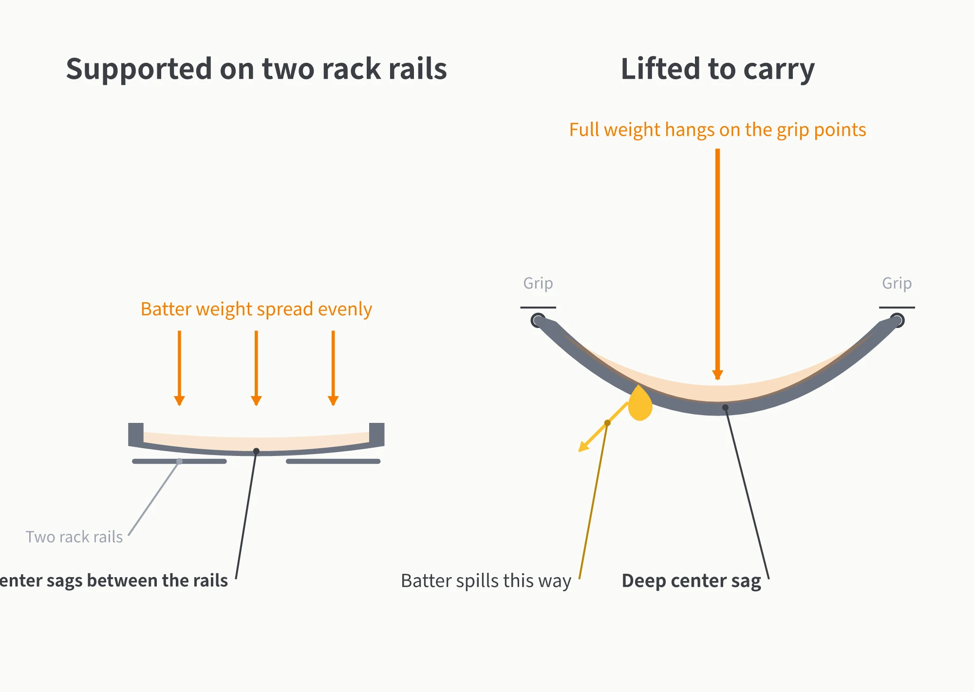
Silicone has a much lower elastic modulus than aluminum alloys. Under identical spans, wall thicknesses, and support conditions, silicone bends much more easily. Bending stiffness scales roughly with the cube of wall thickness. If all other factors remain constant, increasing thickness from 2 mm to 3 mm boosts theoretical stiffness by roughly 3.4 times. However, this does not guarantee that 3 mm will never sag. Pan length, rim cross-section, grip placement, and batter weight all influence the final deflection.
Do not simply ask whether a silicone pan will bend. Ask two specific engineering questions first: Where is the maximum unsupported span? Where will the user grip the pan when carrying it? The answers dictate whether you should optimize the continuous rim, reinforce the base, or supply an external tray.
How Hardness, Thickness, and Metal Inserts Solve Different Problems
Hardness, thickness, and metal inserts all contribute to structural stability, but they are not interchangeable.
Hardness is not a structural load rating. Shore A durometer measures indentation resistance, not the bending stiffness of a full-size baking pan. YueHouDZ typically uses ~50 Shore A as a baseline for silicone kitchenware, and drawings must specify strict hardness tolerances. You must still verify the exact durometer through prototyping alongside demolding requirements, wall thickness, and unsupported span. Assuming a higher Shore number automatically guarantees stability will lead to flawed design choices.
Thickness is an effective lever, but it impacts thermal performance. Adding wall thickness increases sectional bending stiffness, but it also increases thermal resistance. Silicone conducts heat much slower than aluminum. Thicker pan walls alter baking times and crust development. You should never freeze wall thickness based solely on lifting tests without validating baking performance with physical samples.
Metal reinforcement provides a continuous load-bearing path. Designers can integrate a perimeter steel wire, a stamped steel frame, or a full internal skeleton. Metal inserts introduce manufacturing trade-offs beyond added stiffness. You must address insert positioning, overmolding coverage, food contact boundaries, and assembly interfaces during Design for Manufacturability (DFM) reviews. A patented metal insert overmolding process does not apply universally to every insert configuration.
In short, durometer controls material feel and formulation windows, thickness alters sectional stiffness, and metal inserts establish structural load paths. Separate these three variables early so sample reviews avoid guesswork.
Designing a Continuous Rim to Support Lifting Loads
When a user lifts a loaded pan from both ends, check the continuity of the top rim first. If only soft silicone connects the two grip points, the load forces the mid-span downward. Viable design options include widening the silicone flange, thickening the rim profile, inserting a steel wire or rigid frame, or integrating continuous internal supports. No single approach is universally superior or cheaper. Select the design that matches your span, depth, demolding constraints, target unit cost, and intended grip method.
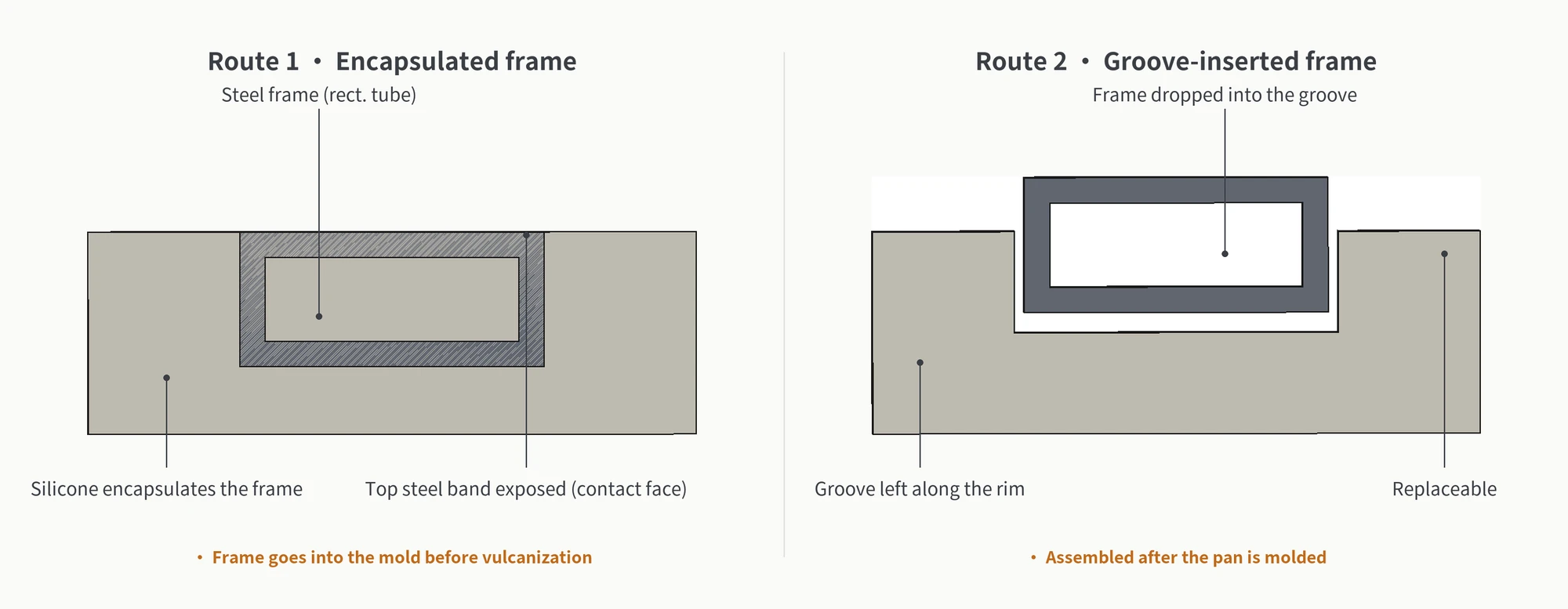
For the compression molding processes covered here, the standard production flow includes rubber compounding, sheet preforming, compression molding with heat and pressure, deflashing, and post-cure if specified. Metal reinforcement branches into two main paths: insert overmolding (placing the frame into the mold cavity before vulcanization to encapsulate target surfaces) or post-mold assembly (molding the silicone body with a retention groove, then snapping in a rigid rim frame). The CAD diagrams below illustrate these two structural principles; they do not represent a specific production cross-section from YueHouDZ or the only available methods.
Small pans still require structural validation; never approve a drawing based on compact size alone. For pans with long spans, deep cavities, or end-lift requirements, treat continuous rim reinforcement as a primary candidate and validate it with fully loaded handling tests. Defining the rim structure on the 2D drawing upfront is far more cost-effective than troubleshooting negative customer reviews after tooling is built.
How Base Design and Trays Influence the Overall System
The base primarily dictates static placement: staying flat on a countertop, landing securely on oven rack wires, and maintaining shape via local ribbing. The base also influences heat distribution. Manufacturers often recommend placing silicone bakeware on a metal baking sheet because the metal provides external support during transfer and helps conduct heat evenly to the mold bottom.
This does not mean base reinforcement is useless for carrying. If base ribs tie directly into the rim and grip points, they contribute to overall bending stiffness. Standalone base ribs usually solve only flat placement and localized sagging between rack wires. Structural effectiveness depends on whether the reinforcement connects to the grip points and how loads transfer through the part.
The diagram below compares the three main structural routes: prioritize a continuous rim for manual carrying, optimize the base for flat placement and thermal transfer, or include an external metal tray when keeping the silicone body flexible. You can combine these routes, but you must validate the final configuration under realistic operating conditions.
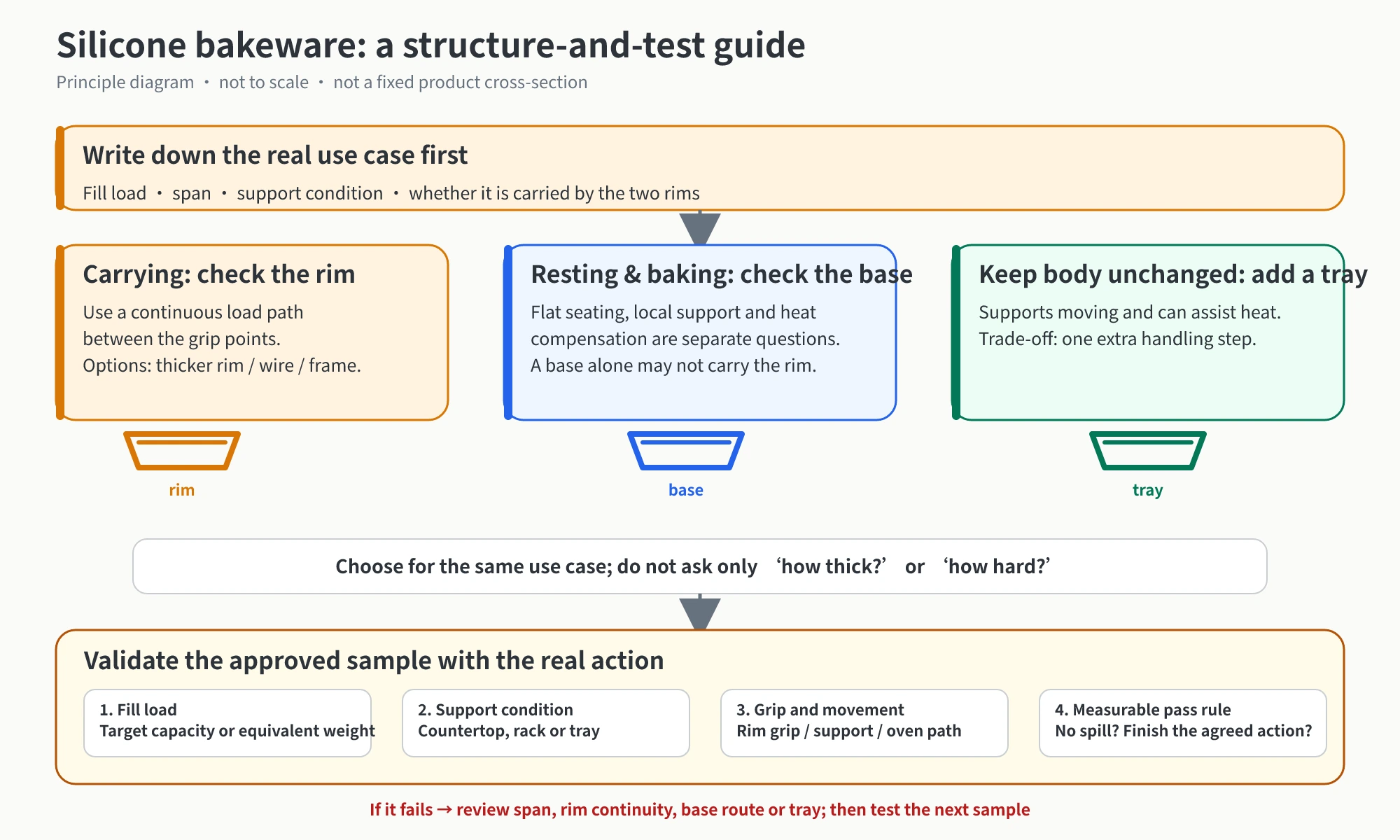
Providing an external tray is not an admission of poor design. For entry-level product lines or projects keeping the silicone body simple, external support is a practical product strategy, even though it requires an extra step from the user. However, if your product promises direct, two-handed carrying from counter to oven, design a rigid rim and continuous load path into the silicone body upfront.
Four Criteria to Validate Carrying Stability on Physical Samples
Industry standards lack a dedicated protocol for testing loaded silicone bakeware during manual transfer. The most reliable approach adapts standard quality inspection protocols: define clear test parameters based on buyer specifications and approved samples before running tests. Lock down these four criteria:
- Fill volume: Test with target batter volume or equivalent liquid weight; empty pan evaluations never predict loaded behavior.
- Support method: Distinguish clearly between testing on a continuous countertop, bare oven rack wires, or a metal baking sheet.
- Grip and transfer: Specify two-end rim pinching, bottom cradling, or the complete transfer cycle from countertop to oven rack.
- Measurable pass criteria: Record quantifiable results, such as zero liquid overflow or deflection limits, rather than vague notes like “looks acceptable.”
If a sample fails, trace the failure mode back to your operating matrix: Is the span too long? Is the rim discontinuous? Is the base structure inadequate, or should the product include an external tray? Root-cause structural adjustments prevent trial-and-error cycles of blindly increasing thickness or hardness.
At YueHouDZ, our Custom silicone manufacturing services cover 2D/3D design reviews, tooling fabrication, rapid prototyping, and volume production for silicone bakeware. For deep-cavity, wide-span, or two-end lift designs, we recommend adding a dedicated “Loaded Handling” line item to your DFM review and locking down these four test criteria before tool steel is cut. This approach integrates real-world handling conditions into your mold engineering before mass production starts.