When a product leaks, many people first blame the sealing ring and assume a different ring supplier will solve it. YueHouDZ has worked in Custom silicone manufacturing for 11 years. After reviewing many leaking product drawings, we keep seeing the same issues. In more than half of the sealing failures we check, the root cause is the groove design, not the ring itself. Most leaks are already decided when the drawing is created. This is especially true in low-pressure hydrostatic applications in consumer electronics, where the product sits in water and takes water pressure. The seal depends on the ring’s rebound force pressing the mating surfaces together. If the drawing doesn’t give enough squeeze, uses the wrong groove, or leaves an uneven surface, even a high-quality Silicone O-Ring can’t generate sealing force.
These five pitfalls are all buried in the drawing. They are listed in the same order used during design: define the groove, set the compression rate, specify tolerances, choose hardness, and leave a path for assembly and validation. Take the drawing in hand and check each item from the first to the last. If the product still leaks after these five checks, then it is time to question the ring quality or production-line assembly. Those are different problems.
1. Groove Dimensions Are Copied or Estimated
We have seen many drawings where the groove was copied from another waterproof housing, while the ring was changed to a larger cross-section diameter. The cross-section diameter is the thickness of the O-ring section. Many factories also call it the “cord diameter.” When the groove and ring are not calculated as a set, the drawing already carries a risk. One common failure looks like this: the product passes room-temperature immersion testing, but during high-temperature aging in summer conditions, the ring swells inside the groove, and the seal fails.
Groove depth and groove width are two separate key dimensions. Groove depth controls the compression rate, or how much the ring is flattened after it sits in the groove. Groove width controls the fill rate. The fill rate is the percentage of the groove cross-section occupied by the ring cross-section. The industry also calls it “groove fill.” The groove can’t be sized so tightly that the ring just fills it. Keep the fill rate within 85% and leave 15% to 25% open space for thermal expansion and oil swelling. If the fill rate exceeds 90%, the ring can swell and lock inside the groove at higher temperatures, leaving no room to create sealing pressure.
How large should the groove be? There is no need to invent the dimensions. Check groove depth and width in GB/T 3452.3. The standard gives ready-to-use reference values: a ring with a 2.65 mm cross-section pairs with a groove depth of about 2.15 mm, and a 3.55 mm ring pairs with a groove depth of about 2.85 mm for static sealing. Groove width is typically about 1.35 times the cross-section diameter. The U.S. AS568 standard and the Japanese JIS standard follow the same logic, but their cross-section series are different. For example, the U.S. 3.53 mm series corresponds to the Chinese 3.55 mm series. Don’t mix standards when copying a drawing. You can also verify the number with a simple formula: groove depth equals cross-section diameter multiplied by one minus the compression rate. For a 3.55 mm ring at 20% compression, the groove depth is 2.84 mm, which matches the 2.85 mm table value. Once the source of the number is clear, any cross-section diameter can be checked. Before copying another drawing, confirm one thing first: whether the ring still uses the same cross-section diameter.
The surface pressed by the ring, often called the sealing band in factories, must not have tool marks or sink marks. For static sealing surfaces, Ra 1.6 to 3.2 is enough. If a sink mark from an injection-molded part falls on the sealing band, water can follow the texture and bypass the ring. The ring itself may be completely undamaged.
2. Compression Rate Is Set by Assumption
The compression rate formula is simple: cross-section diameter minus groove depth, then divided by cross-section diameter. This is also the easiest place to make a mistake. In most cases, 15% to 25% compression gives the best waterproofing result. Too little compression leaks. Too much compression deforms the housing and creates excessive assembly force. Both sides are risky. Once actual compression exceeds 40%, the ring itself is damaged.
The correct value depends on how the ring is installed. If the ring slides into place in radial assembly, it must overcome friction. The more it is compressed, the harder it is to assemble, so compression is usually around 10%. If the ring is pressed directly by a cover in an axial flange design, there is no sliding friction, so compression can reach 20%. Pushing further to 25% to 30% reaches the limit where permanent deformation begins.
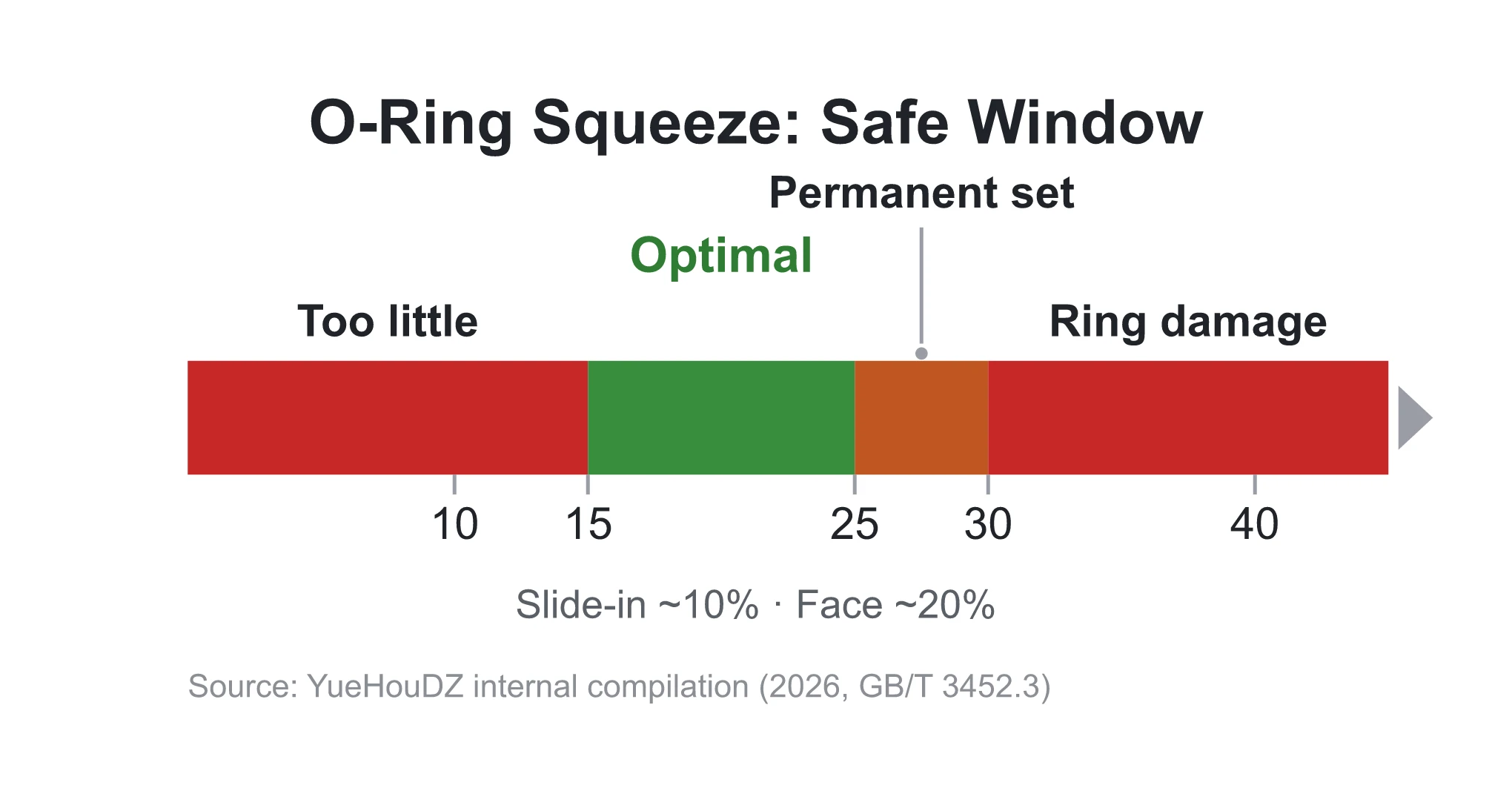
The cost of over-compression doesn’t appear immediately. The industry calls it “compression set.” After the ring stays compressed in the groove for several months, the removed section is flat and no longer returns to a round shape. After longer compression, the section can become butterfly-shaped, and gaps appear on the sealing surface. The higher the compression and the higher the temperature, the faster the ring flattens. The compression rate can’t be increased by guesswork. What looks like a safer tight fit is actually trading away the ring’s service life.
There is another detail that quietly consumes compression. A radially installed ring stretches when it is mounted on the shaft. For every 1% of stretch, the cross-section diameter shrinks by about 0.5%. Once the section shrinks, part of the designed compression is lost. Stretch is usually controlled between 1% and 5%. Japanese and Taiwanese suppliers may call the compression rate the crush rate. It is the same concept, so don’t let the terminology cause confusion when reading design references.
3. Tolerance Stack-Up Is Not Verified
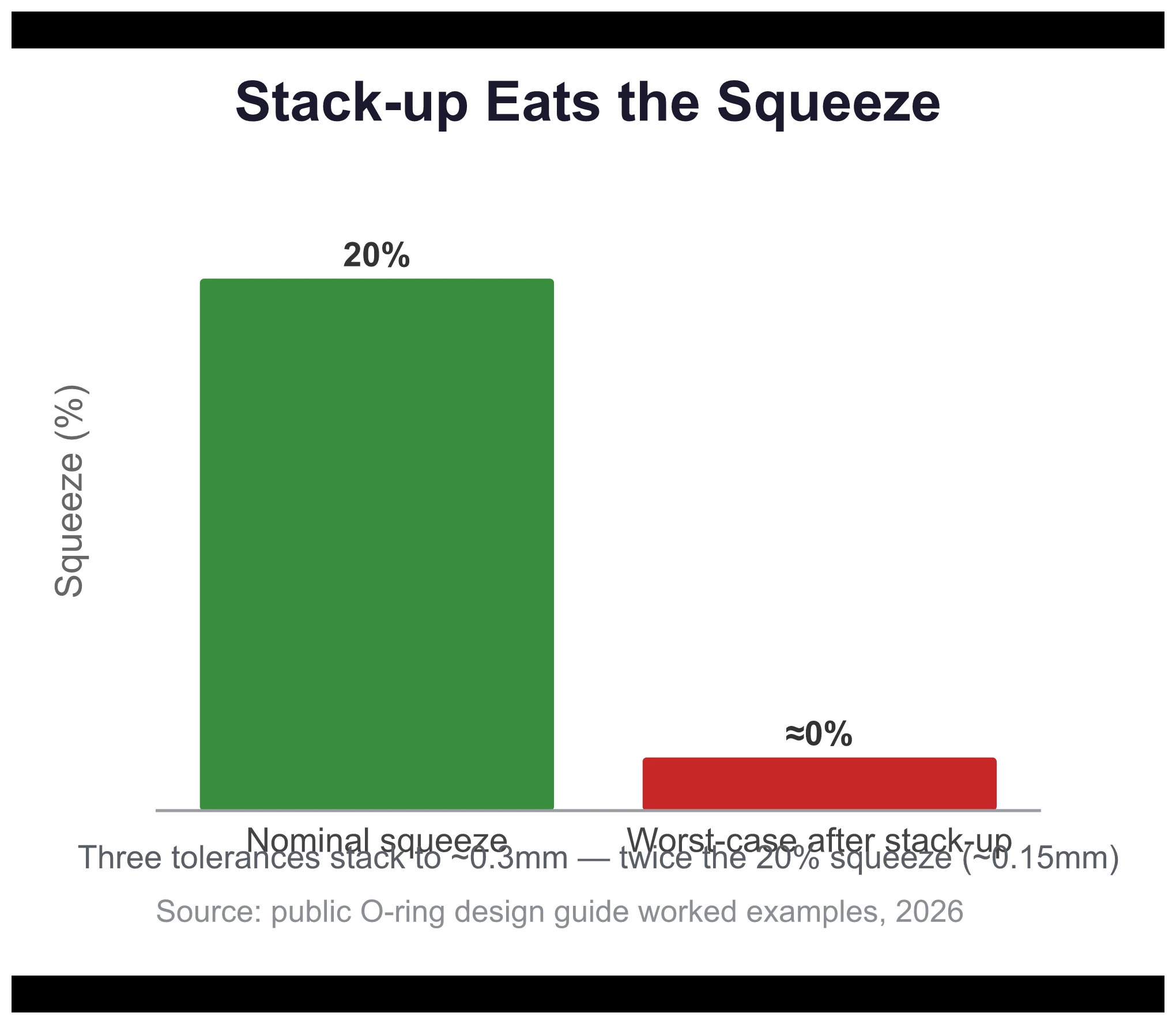
Nominal compression rate is not actual compression rate. Tolerances can eat up half of it.
Apple Rubber gives one example in its design guide. For a ring with a 0.76 mm cross-section, the tolerance of the ring itself, the groove tolerance, and the mating bore tolerance can stack up to 0.3 mm. That is almost half of the ring cross-section. A drawing with a nominal 20% compression rate has only about 0.15 mm of total squeeze. In the worst case, that small amount of squeeze is almost fully consumed. A gap may appear, contact stress becomes insufficient, and micro-leakage starts there.
The most dangerous part of this type of drawing is that it can pass prototyping. Three prototype samples pass immersion testing, the team freezes the drawing, and mass production starts. Then 7 out of 20 samples leak in a 500-piece production lot. The prototype samples happened to fall near the center of the tolerance band, while production dimensions spread across the full range. Prototype approval doesn’t prove that the drawing is correct.
The fix can be completed during drawing review in about five minutes: calculate both limits. This is called worst-case verification. Match the smallest ring with the deepest groove and check whether the compression rate still prevents leakage. Then match the largest ring with the narrowest groove and check whether the fill rate exceeds the limit. If both numbers pass, the drawing can truly pass. When aligning requirements with suppliers later, use these two limit values. Anyone can mark a nominal value.
4. Hardness Is Copied From Another Product
Some people think a harder ring is safer. I’m afraid that’s not right. If the hardness is wrong, leakage can happen in two ways.
If the ring is too hard, it can’t fully conform to the mating surface under low pressure. Its rebound force can’t close microscopic gaps, and hydrostatic testing shows microleakage. Assembly also becomes difficult. Operators may not be able to press the housing closed, and the housing can deform under the load, which makes leakage worse. If the ring is too soft, it fails in another way. It flattens after long-term compression because the compression set is high, and under higher pressure it can be squeezed into the mating clearance and torn. How much can it flatten? A 60 Shore A silicone ring compressed at 120 °C for 1,000 hours can reach a 25% compression set. That is how rebound force is lost step by step. Silicone is not a high-strength material by nature, so hardness and clearance must be controlled together.
What hardness should be specified? Waterproof sealing rings commonly use 50 to 70 Shore A. Consumer electronics housing rings mostly use 45 to 60 Shore A in actual production. A rugged phone design gives a useful reference: the housing sealing ring is around 45 Shore A, while the screw plug uses 70 Shore A. The screw plug doesn’t have broad surface support, so it relies on its hardness to hold the seal. If two ring types on the same drawing use two hardness values, don’t copy the wrong number.
Procurement also needs to track one number: silicone hardness itself usually has a tolerance of plus or minus 5 Shore A. Two suppliers may both mark 60 Shore A, but their actual parts may differ by 5 degrees. Leave room for that variation when specifying hardness on the drawing. Don’t set the compression rate at the limit and bet that every supplier batch will be exact. High-pressure applications have another issue called “gap extrusion,” but low-pressure consumer electronics products usually don’t need backup rings.
5. The Assembly Path Has No Backup Plan
One failure is common: an airtightness test shows a major leak, the product is opened, and the ring has a regular cut mark all the way around. The ring was cut by a sharp hole edge, and the leak sits exactly at that cut. Any sharp edge along the assembly path becomes a knife. The cut may be small, but the leak can be severe.
There are two fixes. Add a 15- to 20-degree lead-in chamfer at the assembly entrance, and add an R0.3 to R0.5 radius transition at the bottom of the groove. If the ring must slide over threads or a hole edge, either add the chamfer into the structure or use a protective sleeve on the assembly fixture. On the drawing, these features are just chamfer callouts. They are not challenging to build into the mold. The hard part is remembering to specify them.
Another common leak point sits on the housing side. When the upper and lower housings use screws to compress the sealing ring, screw spacing is typically controlled at about 35 mm per interval based on industry experience. If the points are too far apart, the middle of the housing arches upward and the sealing surface opens locally. Uneven assembly torque is the same disease in another form. The ring is not damaged, and the groove is not wrong. The housing simply doesn’t press the seal down.
One final step remains: validation. Waterproofing must be verified through repeated testing. A finished product may pass the first test after assembly, then fail after high-low temperature cycling, drop testing, or water pressure testing. Rugged phone design reviews have paid for this lesson. During mass production, validation depends on airtightness testing. The cavity is pressurized, and the pressure drop is measured. Factories call this “air testing,” while the corresponding immersion method is “water testing.” A typical industry method is to fill the product with about 24 kPa of air, hold pressure for half a minute, and pass the product if the pressure drop is less than 0.05 psi. This value is converted from IP67 waterproofing requirements. Water testing takes several minutes per unit and requires drying afterward. Air testing is nondestructive and supports 100% inspection. If the test method and pass/fail line are not planned, the leakage problem will appear only after the customer receives the product.
Remove the Risks Before Drawing Freeze, at No Cost
Which of the five pitfalls should be prevented first? Rank them by cost. Groove and compression-rate issues are frequent, and testing usually catches them. Tolerance issues are the most hidden and the most expensive. They don’t appear during prototyping, but they break out in mass production. By the time customer complaints arrive, the mold investment has already been spent.
The time before drawing freeze has real value. At the drawing stage, changing groove depth, compression rate, or hardness callouts costs nothing. The 3D model can be revised countless times. After tooling, minor mold repairs may cost about $45 to $450. If the groove depth is a molded dimension that can’t be adjusted, the mold has to be remade. That can mean about $450 to $4,500 or more, plus another month added to the lead time. If the issue reaches the customer-complaint stage during mass production, the cost becomes returns plus damaged reputation. The same pitfall can cost 100 times more when it is found late.
Before drawing freeze, checking these five items against the drawing is a free layer of insurance. We are YueHouDZ, with 11 years of experience in custom silicone parts. Our mass-production cases cover instrument housing rings, cable connector sealing, and outdoor waterproof Silicone Seal Ring projects. Seal-structure drawings can be sent to us. We can check groove dimensions and compression rate as part of Silicone parts OEM support, and we do not charge for this step.