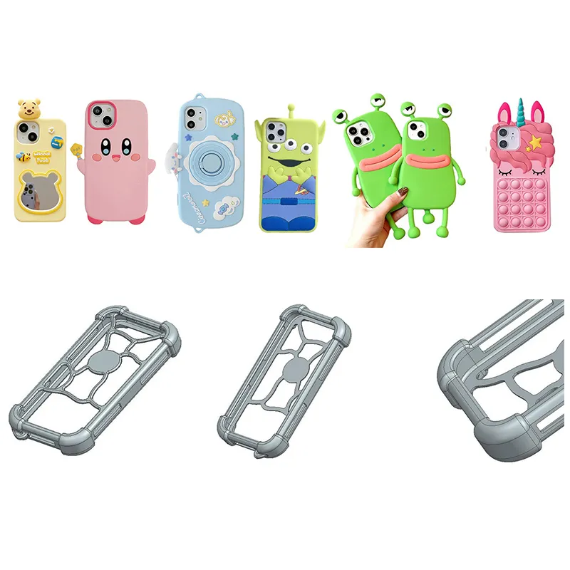
If you have a silicone product idea in mind—a keypad, a seal ring, a protective cover—but every time you try to send it to a factory, you open drawing software, spend five minutes on it, and then close it because you simply do not know how to use it, you are not alone.
Then the idea sits in your head for one month, three months, or half a year. Then nothing happens.
The real issue is not that you cannot draw. The issue is that you assume factories only accept 3D drawings. In reality, silicone product factories receive inquiries every day that include hand-drawn sketches, mobile phone photos of physical samples, or competitor samples sent in with a request to make something similar. A 3D CAD file is certainly helpful, but it is not the price of entry.
This article explains three things: what to put on a sketch so the factory can understand it, what the factory does after receiving that sketch, and which checkpoints you need to watch to make sure the product stays true to the original idea.
Your Sketch Does Not Need to Look Good
The factory does not need artistic skill. It requires dimensional information.
I once visited the design engineering department of a silicone factory in Dongguan. A row of A4 sheets was pinned to the wall. Some showed hand-drawn seal ring cross-sections. Some had keypad outlines drawn in marker. Some were printed product photos marked in red pen with notes such as “this area needs to be soft, around Shore A 50.” Not one of them had been drawn in SolidWorks. One engineer pointed to one sheet and said: the customer spent 10 minutes on this sketch, we spent three days building the 3D model, and once the customer approved it, production moved ahead the same day.
The factory does not move faster because the sketch looks better. It moves faster when the sketch includes the information that matters.
So what exactly needs to be marked?
These Are the Only Things the Sketch Needs to Get Right
Start with the views you have to draw. A front view and a top view are the minimum. You do not need the side view from a full three-view drawing set. Most silicone parts are relatively flat, so two views are enough. You can add a perspective sketch, but that is mainly for your style reference. The factory will not use it for dimensions.
Then mark the dimensions. Do not label every edge you can measure. Only mark three types: mating dimensions, appearance dimensions, and overall length and width. Mating dimensions are the dimensions at the interface where the silicone part fits with another component. Mark these precisely. Asking for ±0.1 mm is reasonable. Appearance dimensions only need a range. A factory can usually handle ±0.3 mm on its own.
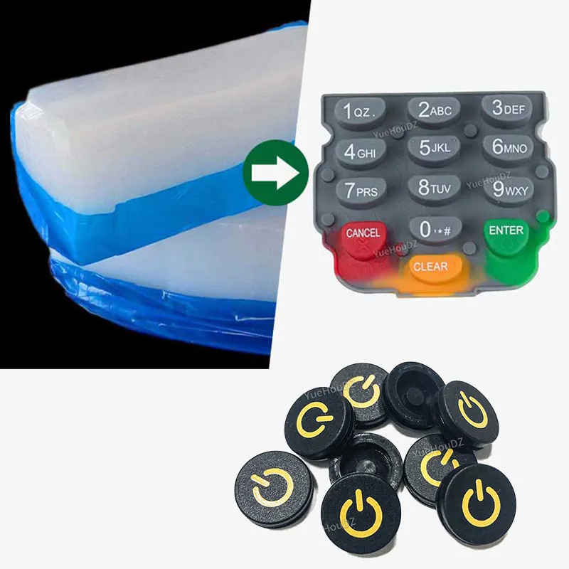
For example, suppose you want to make a silicone instrument keypad that presses onto a tactile switch on a PCB. The one dimension that must be exact is the diameter and height of the contact surface under the key. If that point is off by 0.5 mm, the switch may not actuate. The curvature of the key surface or the size of the edge chamfer only requires a general feel requirement. The factory will confirm those details with you.
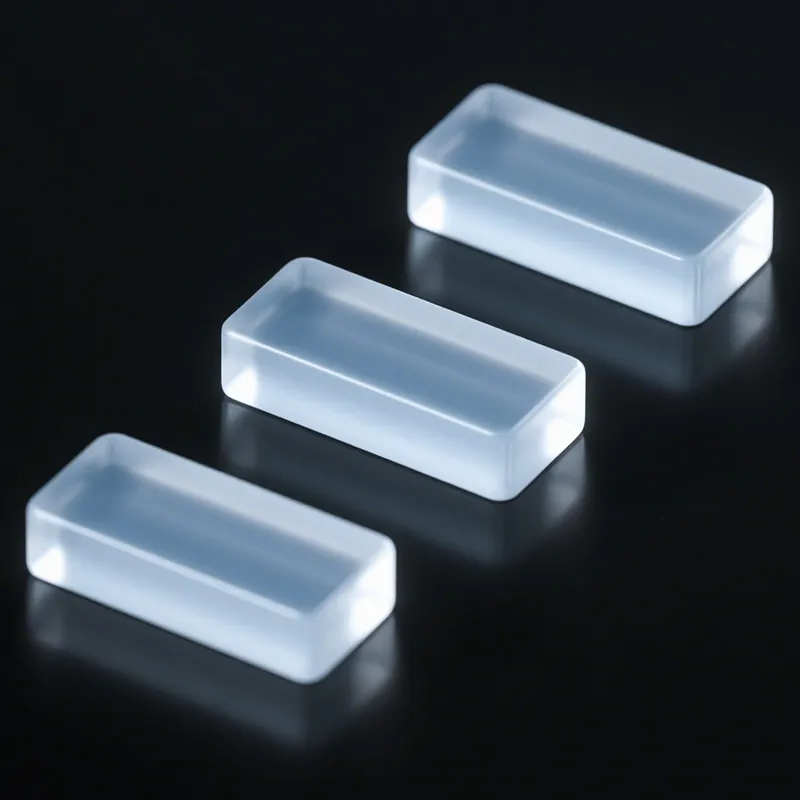
You also need one short note for material and hardness. Do not just write “soft silicone.” Soft can mean Shore A 30 or Shore A 50, and the factory will not know which one you want. Writing “around Shore A 60” is enough. If the part will be used in a high-temperature environment—such as a silicone pad for baking equipment—add “temperature resistance 200°C.” If it will contact food, write “food grade.” You do not need a Pantone color code. Descriptions such as “matte black” or “translucent gray” are enough for the factory to match.
You do not need to calculate silicone shrinkage yourself. Just tell the factory these are the finished-part dimensions. When the factory creates the 3D model for tooling, it will scale the mold by 2% to 3%. On your sketch, simply write the dimensions as finished-product dimensions.
One key piece of information people often skip is tactile feel. Two silicone parts can both be Shore A 70, but if one is 1 mm thick and the other is 3 mm thick, they will feel entirely different. A short note beside the sketch such as “needs a clear tactile snap when pressed” or “should feel very soft and floppy” helps the engineer understand your intent better than dimensions carried out to two decimal places.
What Happens Between the Factory Receiving the Sketch and Sending Back a 3D Drawing
This is where most people have a blind spot. You send over a sketch, and a few days later you receive a 3D drawing for approval. What happened during those few days?
There are roughly four steps.
First, feasibility review. The engineer scans your sketch and runs through several questions: Can this part be demolded? Is the wall thickness uniform? Are there undercuts? Is the selected hardness appropriate? For example, if you designed a silicone sleeve with a wall thickness that jumps from 0.5 mm to 3 mm, the engineer will quickly tell you this area may have filling problems and could show bubbles or sink marks. The suggestion will usually be to add a radiused transition. This is DFM—Design for Manufacturing review. A good Silicone Product Manufacturer will provide a 3D drawing marked with recommended changes at this stage. That is the benefit of working with a silicone product factory that offers real design support. A poor factory will say nothing and build strictly to the sketch. If problems show up later, they treat them as your responsibility.
Second, 3D modeling. The sketch is turned into a 3D model in SolidWorks or Creo. This is purely technical work, and you do not need to get involved. What matters is this: if the sketch is clear, an experienced structural engineer usually needs about half a day to one day to build a medium-complexity silicone part. Custom silicone mold design with a multi-cavity layout or an injection mold with a cold runner takes longer, but that work belongs to the tooling design stage. At the product 3D stage, the factory is modeling the part itself.
Third, shrinkage compensation. Silicone shrinks after molding. Solid silicone typically has a shrinkage rate of about 2% to 3%. When the factory builds the mold 3D model, it scales the product accordingly. You do not need to manage this step, but you can ask one simple question: “What shrinkage factor did you apply?” If the factory can quickly answer “2.2%,” that is a sign it is actually doing the engineering work instead of brushing you off.
Fourth, approval from you. You receive a 3D PDF or a rendering, and possibly a DFM feedback list as well—such as “increase this wall thickness from 1.2 to 1.5 mm” or “add a 2-degree draft angle here.” This is your most important action point: review it carefully and respond carefully. Do not glance at it, think it looks close enough, and reply with “OK.” Approving the 3D model is your one chance to fully align information with the factory. After that point, the next stop is steel tooling.
By the way, this is also how YueHouDZ handles silicone product design consultation. You can send in a sketch or a photo. The engineering team first provides a DFM review, then prepares a 3D drawing for your approval. There is no design consultation fee at this stage. Quotation and tooling only begin after you confirm the 3D. That lowers your decision risk. You do not need to pay tooling costs first. You move forward only after reviewing the 3D and confirming that the product can be made.
During Tooling and Sampling, Watch These Three Checkpoints
After the 3D model is approved, the project moves into tooling development and sampling. Mold machining usually takes about 3 to 7 working days. At this stage, you may feel like you are just waiting for updates, but there are three things you need to handle yourself. Miss them, and you may not get the right product.
Checkpoint 1: Tooling design confirmation. The factory will confirm several items with you: what steel to use, how many cavities to open, and where the parting line will be located.
There is a simple cost-saving logic here: be clear about your volume first. A project for 500 units per year and one for 50,000 units per year should not use the same cavity count or the same tooling plan. Do not ask the factory to “build for the maximum future volume” right away. You pay the full tooling cost upfront. If the mold is oversized, you may never use that capacity.
There is also a practical cost-down approach for small-volume programs. If expected annual sales are only 1,000 to 2,000 units, a 1- or 2-cavity mold with tool dimensions kept within 300 × 300 mm can usually keep tooling cost in the range of about $450 to $2,200. The same product, if designed as an 8-cavity mold for high-volume output with a mold size of 800 × 600 mm, starts at about $2,963. Do not downgrade the tooling material—P20 is the baseline. Reduce mold size and cavity count instead.
Checkpoint 2: T0 trial molding. After the mold is completed, the first trial run produces the T0 sample. At this point, focus on three things: does the tactile feel match the target, are there any obvious cosmetic defects, and do the assembly dimensions fit the mating parts? T0 is usually not expected to be perfect. Flash, incorrect color, or minor surface defects are normal. You report the issues, and the factory adjusts the mold.
Checkpoint 3: T1 revised sample. The issues identified in T0 are corrected in T1. If the T1 sample meets your expectation, sign off on the golden sample. That approved sample becomes the one and only reference standard for the entire mass-production cycle. No matter how many production batches are made later, the standard is that one sample.
One more reminder: there is always a time gap between samples and mass production. Silicone materials can show slight batch-to-batch shrinkage differences. Different colors can vary by as much as 0.3 mm. When the first carton of mass production is ready, compare it directly against the approved sample. If you see a difference, talk to the factory immediately. Early-stage mass production is still adjustable.
After the Sample Passes, How to Keep Mass Production from Drifting
A sample is made right once. Mass production means making the same thing over and over. The control logic is different.
Do these three things up front:
Sign and seal the approved sample. After sample approval, both you and the factory should keep one signed golden sample. This is not a formality. For any batch that arrives later, the only valid acceptance standard is the difference between that batch and the approved sample. Without a golden sample, you may say, “this batch is thicker than the sample,” and the factory may reply, “no, this is how it is.” Neither side has a hard reference.
Write critical dimensions into the contract. Not every dimension needs CPK control. Choose two or three mating dimensions—the ones that would scrap the whole product if they go out of spec—and state their tolerance range and CPK requirement in the contract. A common standard is CPK ≥ 1.33. Cosmetic dimensions can be controlled by AQL sampling. They do not need 100% measurement.
Inspect the first production batch in person. If you are in China, visit the factory during the first mass-production run. If you are overseas, assign a QC inspector or ask the factory to send the first production carton for approval.
Mass production uses the same mold as the sampling stage. Once process parameters are stable, consistency is usually manageable. But no one can guarantee the first batch without verification. You, or someone you appoint, needs to see it before release.
Has Anyone Really Turned a Single Sketch into Boxed Product?
Yes. More often than you might think.
More than one of our customers started with nothing more than a sheet of A4 paper—a pencil outline of a keypad, with notes such as “make this area a little more raised” and “about 5 cm long.” Based on that sketch, the team created the 3D model, the customer approved it, the mold was built, and that keypad is now in its third year of shipments.
A designer and 3D software should never be the barrier that stops a project from starting. There is only one real barrier: whether you are willing to spend 10 minutes putting the idea in your head onto paper. Thereafter, hand it over to a factory willing to take the project from sketch to finished product with you. Contact Us.