You sent the drawing to a Silicone Product Manufacturer. You paid the mold cost. Two weeks later, the samples came back.
You open the package and find the dimensions are off by 1.2 mm. The groove in the seal ring is full of flash. One swipe of a fingernail peels off a strip of silicone. Worst of all, the parting line cuts straight through the center of the logo. A thin line runs through the letter “O,” making it look like a printing defect.
The silicone factory says, “We built the mold according to your drawing.”
That is not wrong.
The machine tool holds 0.01 mm accuracy, but the mold cutter doesn’t know your design intent. It only sees where that line sits on the drawing and what number is marked next to it. The following seven checks should be done before you hit “send.” Miss any one of them, and the mold stage will turn into a cash expense.
1. Is the material requirement clearly written?
If the drawing you send to the silicone factory only says “silicone product,” it says almost nothing.
Silicone is not one material. It is a material family. A single factory may have five or six silicone compounds running at the same time, with hardness ranging from Shore A 30 to 80, temperature resistance from -55°C to +280°C, and big cost differences between food-grade and non-food-grade materials. The few words you write in the drawing notes determine which compound goes into the compression mold.
Hardness is the first thing that must be specified. A keypad made at Shore A 50 feels entirely different from one made at Shore A 70. Shore A 50 is softer. It feels more cushioned when pressed, but rebounds more slowly. Shore A 70 is firmer and snaps back faster, but long-term use can tire the fingers. If you don’t know the exact value, give a range—for example, “50–60 Shore A, tactile feel takes priority.” Do not write “medium hardness.” Those two words are one of the most frustrating notes a silicone factory can receive.
Temperature resistance is the second point. Standard VMQ silicone works between about -40°C and 120°C. If the product must operate for long periods at 200°C—such as a sealing strip for baking equipment—the drawing should clearly state “high-temperature silicone” or a fumed-silica reinforced grade. The supplier decides between precipitated silica and fumed silica based on the temperature range written on your drawing. Use the wrong material, and it may powder in three months.
Food-grade requirements are the easiest to miss. If the product contacts food—such as a kitchen silicone spatula, oven mat, or jar seal ring—the drawing must clearly state “food grade” and list the required standard: FDA, LFGB, or both. If that information is not on the drawing and you ask for an FDA report after the mold is already built, everything depends on whether the raw material already has the required certification. If it does not, switching to a certified compound and making samples again wastes both time and mold cost.
In one sentence: in the material field of the drawing, at minimum write the hardness, the temperature rating, and whether it must be food grade or medical grade. The rest can be discussed with the factory, but without those three items, the factory has no basis for judgment.
2. Do not apply metal tolerances to silicone parts
This is the mistake engineering-driven buyers make most often—using CNC metal machining tolerance logic for silicone parts. They mark ±0.05 mm on the drawing, and the mold shop calls to say, “We can’t make this to that tolerance.”
In the mold, silicone is heated, cured, and then demolded. After demolding, it continues to shrink. Typical shrinkage runs from 2% to 4%, depending on the compound and curing process. That does not yet include the extra 0.2% to 0.5% from secondary curing, or post-curing. ISO 3302-1 states this clearly—because shrinkage variation is large, M1 and M2 precision classes for silicone and rubber products are very difficult to achieve. M3 is the usual recommendation.
What does M3 mean? For dimensions under 10 mm, the tolerance is ±0.10 mm. For 10 to 20 mm, it is ±0.15 mm. For 50 to 100 mm, it is ±0.35 mm. If you specify ±0.05 mm, you are asking for M1-level precision. That usually requires a metal mold, LSR injection molding, and tight control of every material batch.
When setting tolerances, remember one rule: separate critical dimensions from general dimensions. Leave tighter control for compression on the sealing surface and for fit-up gaps. Relax appearance dimensions as much as the design allows. If every dimension is marked as precision, then nothing is truly prioritized. The factory won’t know which dimensions really matter. The result may be tight control in unimportant areas and loose control where the seal actually matters.
There is another detail. If the dimensions on your drawing are final part dimensions, state clearly in the notes whether “dimensions already include shrinkage compensation” or “mold maker must apply shrinkage compensation.” If you do not say so, the silicone factory will usually enlarge the cavity by a default shrinkage rate of 2% to 3%. If your dimensions were already enlarged, the part gets compensated twice.
3. Straight walls plus zero draft equals torn demolding
Draft angle is one of the easiest items to miss on a drawing because it does not affect the product’s appearance or function. It only impacts whether the part can actually be made.
Silicone is soft, so many people assume soft materials demold easily and do not need draft. That is not how silicone compression molding works. The process runs at 150°C to 200°C. After the material cures in the mold, the product has to be removed while still hot. If your deep cavity has four vertical 90° walls, demolding is like pulling a carrot out of frozen ground. The silicone surface will scrape against the mold wall and leave drag marks.
The taller the part, the less draft can be skipped. For shallow parts under 10 mm, 0.5° to 1° may be enough. For a 25 mm cavity, at least 1.5° is safer. For deep cavity parts above 50 mm, start at 3°. This has little to do with whether the finished product feels soft or firm. A softer elastomer can actually create more friction during demolding because deformation increases the contact area.
If a structure truly cannot accept draft—for example, one face must stay perfectly vertical as a locating surface—then add draft to the other three faces at minimum. In the drawing notes, tell the mold shop clearly: “The 0° face is the locating face. Demolding drag marks are possible. Please plan for mirror polishing or increased ejection area.” Mold makers are not afraid of difficult geometry. What causes trouble is not knowing where the problem will show up.
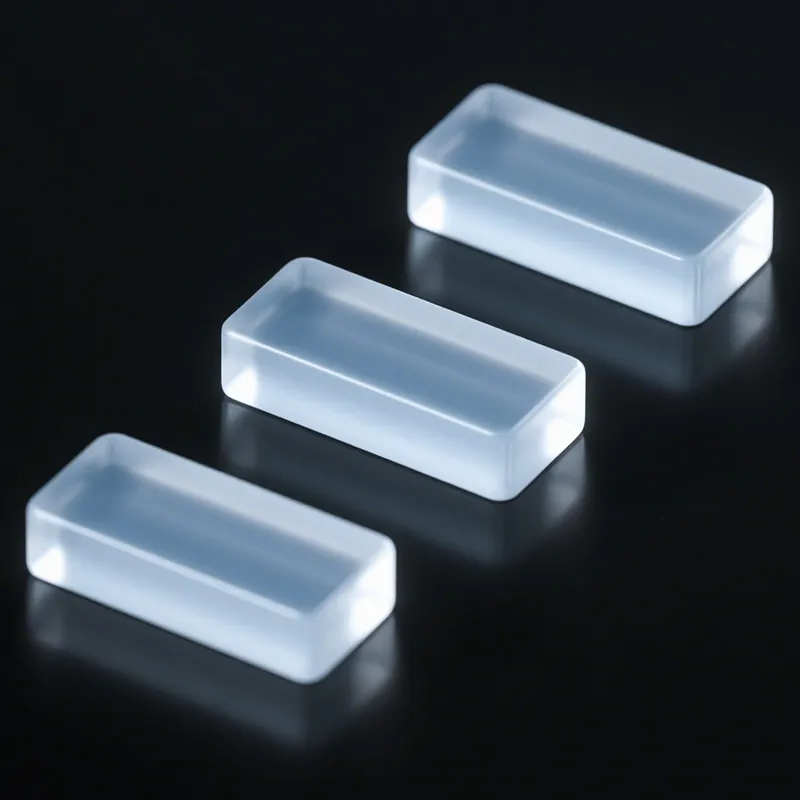
4. Where is the parting line?
The parting line is the joint between the upper and lower halves of the mold. Silicone compression molding runs under pressure. The compound heats up and expands in the cavity, then gets squeezed into the gap between the two mold halves. After cooling, it leaves a ring of flash on the product surface. This line will always exist physically. You can only decide where it goes. You cannot make it disappear.
The consequences of a badly placed parting line range from minor cleanup to direct scrap.
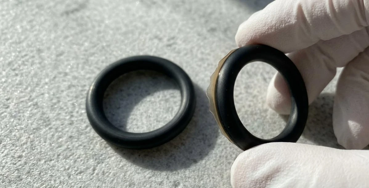
If the parting line crosses a sealing surface—such as the lip of an O-ring, the contact face of a sealing strip, or the mating face of a waterproof button—you are building a natural leakage path into the sealing structure. Silicone flash has poorer elastic performance than the main body. Under compression, it ages and cracks earlier. Once it cracks, you have a gap.
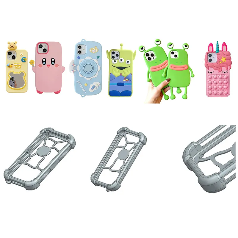
If the parting line crosses a cosmetic surface—the front face of a protective cover, the character area of a keypad, or the logo location—the trimmed edge never looks fully clean. Silicone flash is very thin, usually 0.02 to 0.1 mm. Even after trimming, burrs can remain to the touch, and a visible line usually stays on the surface.
The best approach is to place the parting line on the largest contour line of the product. Keep it on flat areas whenever possible, not across curved surfaces. If it must cross a curved surface, use stepped parting or contoured parting instead of a straight cut across the form. If there is a flash requirement on a critical area—for example, “flash height on sealing surface ≤ 0.05 mm”—write it in the drawing notes. Then the mold shop will know that location needs a tight shutoff, not a standard parting surface.
You do not need to draw the mold parting line in full on the part drawing, but you do need a clear idea of where it will likely run. If you are not sure, send the 3D file to the silicone factory and ask directly where they plan to split the mold. Confirm that first, then move ahead.
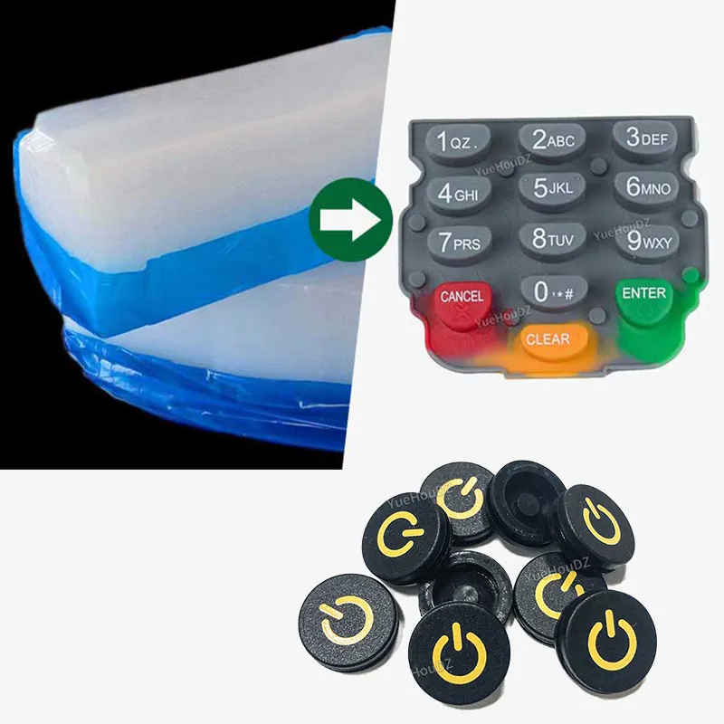
5. Is the surface finish matte, textured, or polished?
Many buyers assume silicone products come out of the mold with a sandblasted texture. They do not. That texture comes from the mold surface after blasting or texturing. Silicone itself normally cures with a semi-gloss finish, not a matte blasted surface. Sand texture, mirror polish, leather grain, and etched patterns all come from the texture on the mold steel surface. This differs from plastic parts. Plastic can be treated after molding. Silicone usually cannot. Silicone surfaces naturally resist inks and coatings, so post-process surface finishing costs much more than cutting the texture directly into the mold.
The finish you want must be written clearly on the drawing. If you do not specify it, the mold shop will usually default to a fine sandblasted texture because it is the most universal option. But “fine sandblasting” can vary greatly from one shop to another. One factory may use #220 media, which is relatively coarse. Another may use #400, which is much finer. The most accurate way is to specify a roughness range—for example, “Ra 0.4–0.8 μm, matte blasted appearance”—or simply provide a photo of the exact texture you want as a reference.
If you are making laser-etched characters—common on Silicone Keypad remote controls—then you are not dealing with one surface requirement, but two. One is the base material color and finish. The other is the color revealed after laser etching removes the top layer. For example, if the keypad is dark gray with a matte finish and the etched characters must transmit light, the drawing should separately state: “Base material: gray (Pantone 425C), matte finish, Ra about 0.4 μm; laser-etched area: remove dark gray top coating to expose the semi-translucent natural silicone below.” These two requirements stack. If they are not specified clearly, uneven character color in production can result in a full batch rejection.
6. Which dimensions cannot change?
A drawing may contain dozens of dimensions, but not all of them matter equally. If you do not identify which ones are critical, the processing side will assume they are all equally important—which means none of them are truly prioritized.
Critical dimensions usually fall into a few categories: compression on the sealing surface, which determines whether the seal leaks; fit clearance on mating surfaces, which determines whether two parts can assemble; keypad actuation force and travel—often specified as “design actuation force 100 g ±25 g”—which determines tactile feel; and wall thickness, which affects whether the product feels soft and collapsible or firm and supportive.
Mark critical dimensions separately, and assign them their tolerances. Do not force one general tolerance across every size. For example, on a Silicone Seal Ring, the inner diameter on the mating surface might be ±0.10 mm, the outer diameter on a non-mating side might be ±0.30 mm, and the height in the compression direction may need to be tighter at ±0.05 mm. When these three dimensions are highlighted separately, the mold shop can tell at a glance which one should be tuned first and which one can remain more open.
7. What else is missing from the drawing?
The last check is not about one specific dimension. It is about whether the drawing is missing supporting information.
Is the color identified by Pantone code? Writing “black” is not enough. In silicone, “black” can mean charcoal black, gloss black, or conductive black, depending on the amount and type of carbon black added. Write the Pantone color code or provide a physical color chip.
Is the unit clearly stated—mm or inch? Silicone factories often receive inch-based drawings from overseas customers, while the workshop floor uses metric equipment. State the unit system clearly in the title block. Send a STEP file rather than only images so the factory can import the model directly into programming.
Have you stated the expected volume? A note such as “initial 500 pcs for sample verification, followed by 5,000–10,000 pcs/month” helps the mold shop decide how many cavities to build, what mold steel grade to use, and whether the mold base needs inserts. The same silicone seal ring requires an entirely different mold concept for a 500-piece pilot run than for 100,000 pieces per month in mass production. Volume determines mold life design. Putting that information on the drawing helps the factory make the right call.
Drawing Self-Check List Before Printing or Sending
- [ ] Material: hardness (Shore A), temperature rating, and whether food grade is required are all specified
- [ ] Tolerances: critical dimensions are marked separately, and tolerances follow silicone standards (ISO 3302 M3), not metal machining precision
- [ ] Draft: deep cavities have at least 1.5°, shallow parts have at least 0.5°, and any zero-draft faces have been disclosed to the mold shop
- [ ] Parting line: its likely location is understood, and it does not cross the sealing surface, logo area, or main cosmetic face
- [ ] Surface finish: roughness is specified clearly or a reference photo is provided; avoid vague terms such as “medium” or “standard”
- [ ] Critical dimensions: sealing surfaces, mating surfaces, and button force are highlighted separately with independent tolerances
- [ ] Supporting information: Pantone code, units (mm), expected volume, and STEP-format file are all included