In the early communication stage of customized silicone products, file format issues often become a “roadblock” that delays project kick-off. In real projects, we frequently hear feedback from customers such as: “The factory cannot open the 3D file I sent. They said the format is wrong, which delayed the mold opening schedule.” According to industry research, about 60% of customized silicone projects experience initial process delays due to format issues, which directly affect design communication and delivery lead time. This content is compiled from YueHouDZ factory’s practical experience in customized silicone product projects, and is provided as a reference for your early-stage decision-making.
Why Is the STP Format the “First Choice” for Silicone Product Mold Machining?
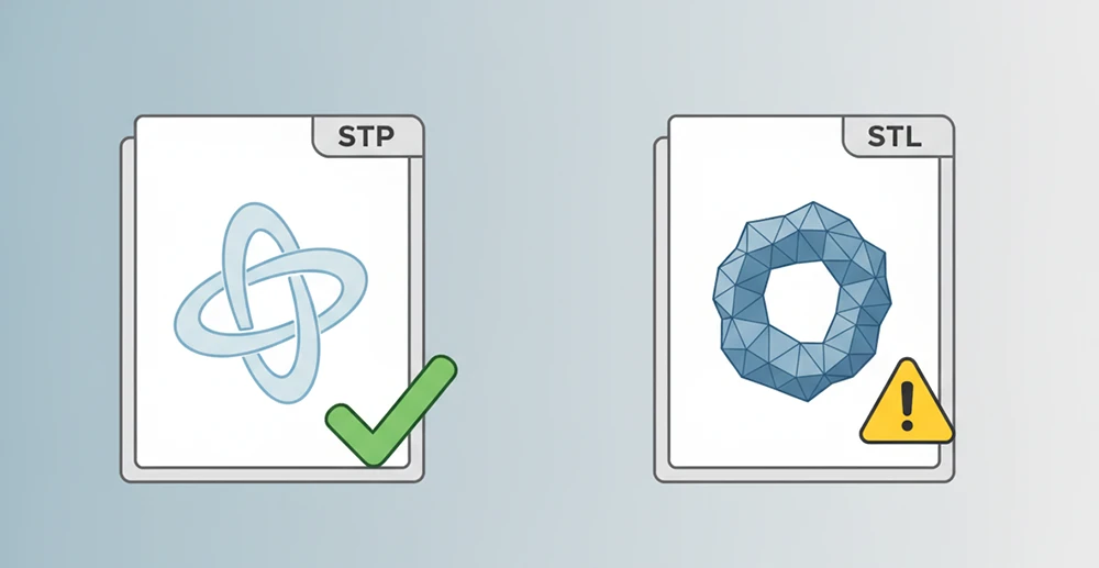
In the field of silicone mold machining, the STP (STEP) format is widely regarded as the “gold standard”, mainly due to its parametric characteristics. Compared with mesh formats such as STL, STP files fully retain the design’s dimensions, features, and parametric relationships. Engineers can directly modify details such as hole diameters and chamfers without rebuilding the model from scratch. As the industry consensus goes, “STL format is suitable for 3D printing but not for mold machining. STP format is a parametric and editable model, so STP format is required to ensure machining accuracy.”
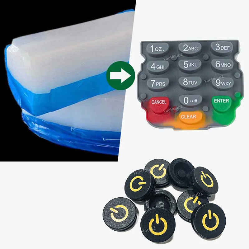
For example, when a customer customized silicone keypads with complex textures, it took only 2 hours to adjust the key height based on the STP file. However, using the STL file would have required 2 days to rebuild the model, highlighting a significant efficiency gap.
Common File Formats for Customized Silicone Products and Recommended Priority Order
Based on YueHouDZ factory’s compatibility testing of mainstream mold design software such as UG and SolidWorks, the commonly accepted formats can be ranked in order of priority as follows: 1) STEP (STP); 2) IGES (IGS); 3) Parasolid (XT); 4) SolidWorks (SLDPRT). The specific basis for this ranking is:
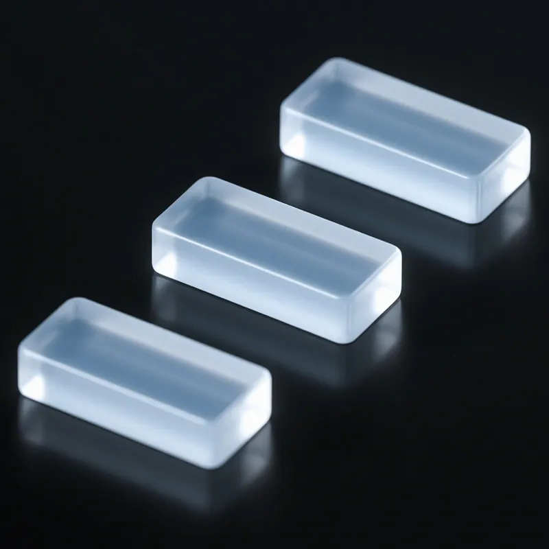
- STP format: Can be directly read by 98% of professional mold software, with a data integrity rate of up to 99% and no risk of parameter loss. It is especially suitable for precision parts such as silicone sealing rings.
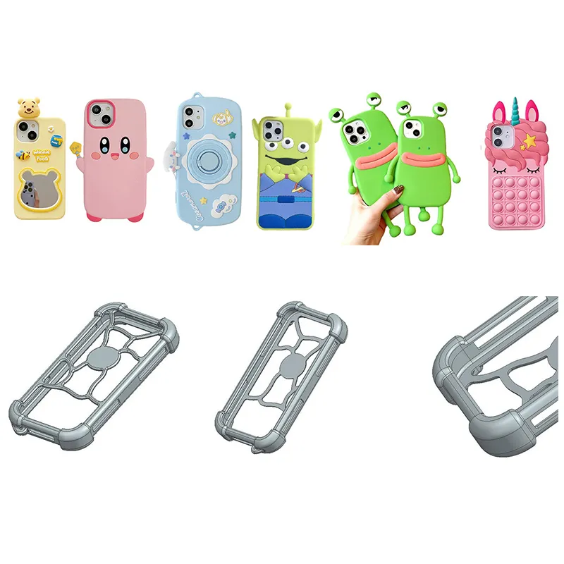
- IGES format: Compatible with about 90% of software, but when converting complex surfaces (such as the curved form of silicone wristbands), approximately 5% of details may be lost. It should be used with caution for surface-driven designs.
- XT format: Since it shares the Parasolid kernel with UG and SolidWorks, it preserves parameters more completely. In precision silicone product customization, the parameter retention rate is about 15% higher than IGES
- SLDPRT format: Version compatibility must be considered (files created in higher versions may not open in lower versions). It is recommended to provide a STEP backup file at the same time.
When customers submit files, prioritizing this order of formats can minimize issues arising from format conversion.
Warning: “Distortion” Risks Caused by File Format Conversion
Non-professional format conversion can easily cause loss of file information and directly affect machining accuracy. The most common issues fall into two categories:
- 2D file conversion: For example, converting “AI to JPG”. After converting a vector file to a bitmap, precise measurements are no longer possible. There was a case where a customer used a JPG image to customize silicone gaskets. Due to blurry dimension markings, the finished product apertures were 2 mm smaller than required. As a result, the entire batch of molds was scrapped, and a new mold opening was delayed by 15 days.
- 3D file conversion: This requires even more attention. For instance, when manually converting an STL file to an STP file, problems such as broken surfaces and missing chamfer features often occur. Such broken-surface defects caused by non-professional conversion account for about 30% of format-related issues in the industry. In one case, a customer converted an STL model of a silicone sleeve to STP, and the inner wall of the model had 7 broken areas. The engineer spent 2 days repairing the model, directly affecting the mold machining schedule. In addition, converting XT files using lower-version software may cause loss of parametric information, making it impossible to modify dimensions later.
Solution: It is recommended to use native software such as SolidWorks or UG for conversion. After conversion, run the “model check” function to focus on verifying surface continuity and feature integrity. Avoid using online conversion tools (which can have data loss rates as high as 20%).
Conclusion
In customized silicone products, always keep the following three principles in mind when selecting file formats:
- 1. Prioritize STP format: Parametric characteristics ensure editability and machining accuracy, reducing the risk of rework.
- 2. Use compatible formats as secondary options: Choose IGES, XT, and SLDPRT in that order, and pay attention to software version compatibility and the complexity of surfaces.
- 3. Reject non-professional conversion: Submit original formats directly whenever possible, and involve professional engineers in conversions for complex models.
Only by following these principles can you avoid the “the file is not in STP format so it cannot be opened” problem, ensure a smooth process from design to machining, and ultimately guarantee both product quality and delivery schedule.