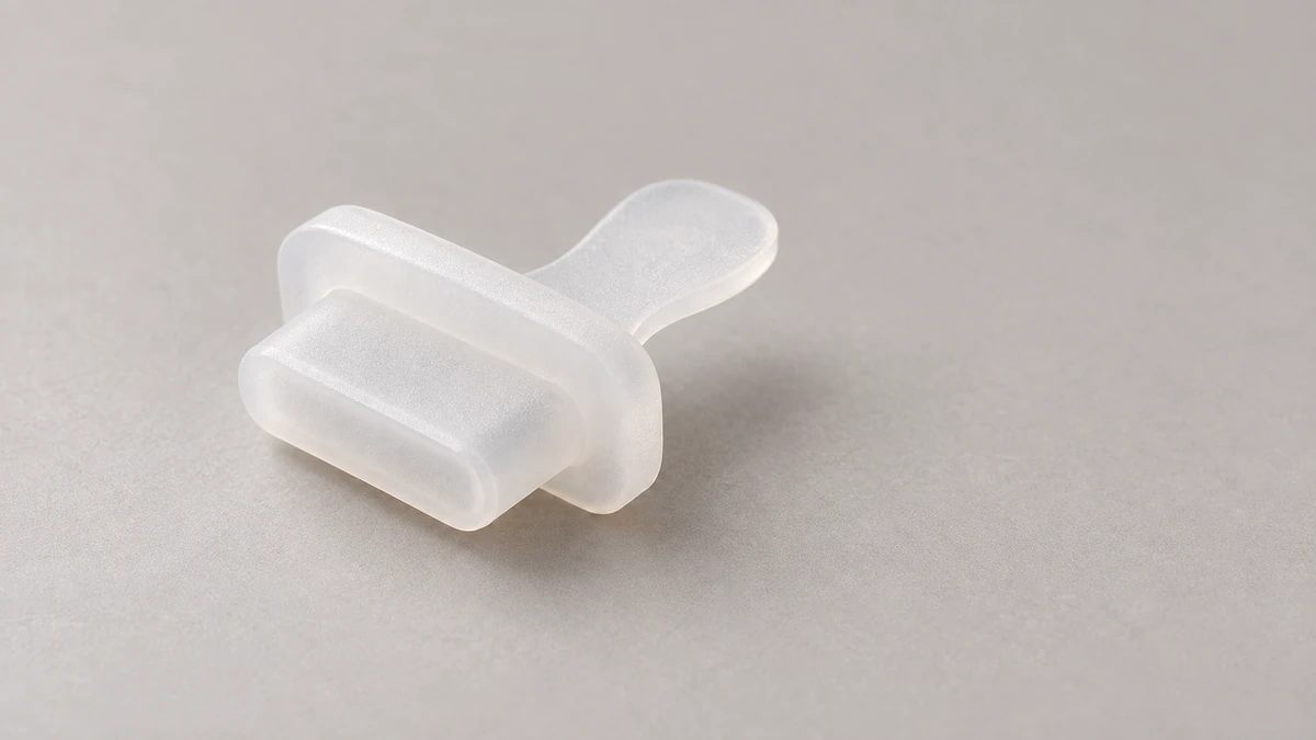
When sourcing a USB Silicone Plug for a device, people often blame bad prototype feel on one factor: picking the wrong silicone durometer. If it won’t go in, they switch to a softer compound; if it falls out, they switch to a harder one. That fix sometimes works temporarily, but often just trades one failure mode for another.
Because “won’t insert” can point to two entirely different issues. A slender insertion tip that is too soft will buckle at the port opening under axial force—a mechanical failure known as elastic instability or buckling. On the other hand, if the tip enters but the dimensions are too large or the contact length is too long, resistance builds up as you push. That stems from excessive interference or high friction. Interference is the dimensional difference between the plug and the port opening; this exact dimensional difference generates the radial compression force that holds the plug in place. Conversely, if a plug inserts smoothly but falls out easily, the issue might not just be soft material—it could be insufficient contact interference or partial contact with the cavity walls.
YueHouDZ helps customers verify the actual contact zones on compression-molded silicone parts using physical connector samples or 3D CAD files and arranges functional prototype verification. For these dust plugs, you must evaluate dimensions and durometer separately: dimensions dictate how much the silicone compresses, while durometer determines the pushback force after compression. One cannot replace the other.
Identify the Exact Dust Plug Failure Mode First
If a sample feels wrong, classify the issue into one of these categories before adjusting dimensions or durometer:
| Sample Symptom | Likely Root Cause | First-Pass Troubleshooting |
|---|---|---|
| The tip stops at the port opening and bends immediately upon pushing | Slender tip, insufficient root support, lack of lead-in chamfer/radius, or overly soft material | Check if the tip buckles first, then decide whether to add structural support, modify lead-in geometry, or increase durometer |
| Inserts smoothly but falls out with light shaking or after a few cycles | Insufficient interference, misaligned contact area, or poor material rebound | Measure actual contact dimensions of both port and plug; check if the loose-fit extreme loses contact |
| Requires heavy force to insert and pulls out with difficulty | Excessive interference, overly long contact length, high durometer, or sharp port edges causing drag | Inspect the tight-fit extreme, check port lead-in radius, and inspect for friction marks |
| Edge stress whitening, flash/burrs, or tearing | Sharp port edges, poor parting line placement, rough contact surface, or localized over-compression | De-burr port entry and polish mold surfaces before considering material changes |
The most common confusion happens between the first two symptoms. A soft, slender tip might buckle at the entrance, making it seem “too soft to push in.” That same soft material, once inside, might fall out due to weak retention force. For buckling, prioritize lead-in geometry, check the aspect ratio, and reinforce the root. For loose fits, focus on interference dimensions and durometer. Don’t lump both issues under “bad soft material.”
When a plug is hard to remove, examine the surface marks. If extraction resistance starts high immediately, check dimensions, contact length, and lead-in chamfers first. If one side shows heavy scuffing, inspect for eccentricity, sharp edges, and parting lines. You only need to check for vacuum lock on deep-insertion, large-contact closed designs where air cannot vent. Never treat vacuum suction as the primary culprit for shallow-insertion port plugs.
Calculate Dimensions First, Screen Durometer with Samples
A USB port is not a simple round hole. The plug body may rely on top and bottom faces, side ribs, thin lips, or local detents for retention—all while clearing the internal plastic tongue with electrical contacts. Therefore, you cannot summarize the fit by subtracting the port opening from the plug diameter, nor can you copy compression ratios directly from O-ring design guides. Here, compression ratio means the percentage of cross-sectional deformation when silicone is compressed.
Define two dimensions along every real contact vector:
P: The dimension of the plug’s contact feature (such as the outer distance between top and bottom ribs).O: The dimension of the matching port opening or internal cavity.
Manufactured parts fluctuate within allowable tolerance limits rather than matching nominal drawing values. You must calculate two extreme combinations:
Loose-fit interference = P_min − O_max (the smallest plug in the largest port).
Tight-fit interference = P_max − O_min (the largest plug in the smallest port).
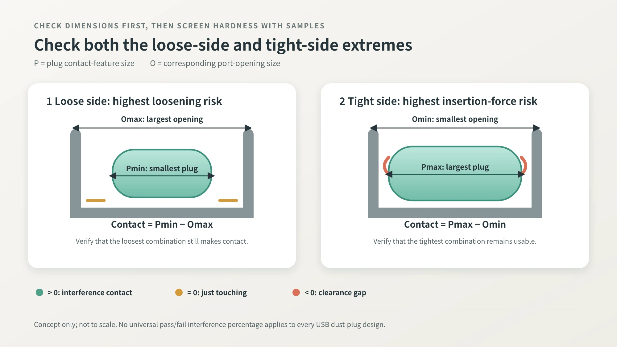
A positive calculation means the port compresses the plug. Zero means line-to-line contact. A negative value indicates a clearance gap. When loose-fit interference drops to zero or below, mass production will yield parts that fail to touch the cavity wall and fall out with light movement. Conversely, if tight-fit interference is too high, insertion force, pull-out force, and edge wear will escalate. There is no single universal maximum interference percentage for all USB dust plugs; geometry, material, contact length, and empirical testing dictate the upper limit.
To compare concepts, calculate the nominal interference ratio as Interference ÷ Plug Dimension along that axis. This ratio only reflects the nominal envelope relationship between plug and port; it does not equal the true internal compressive strain of ribs, lips, or hollow sections. Use this metric to benchmark variants within the same project, but do not treat O-ring handbook recommendations as pass/fail criteria. Silicone Rubber O-Rings sit in dedicated grooves with distinct sealing and loading mechanics compared to localized ribs inside a rectangular connector. Borrow the calculation logic, not the absolute numbers.
Once dimensions are checked, select sample hardness levels. Product literature for consumer and industrial silicone plugs, sleeves, and grommets often references durometers from 30 to 60 Shore A. Shore A measures the hardness of soft elastomers; higher numbers indicate stiffer material. Use this range only for initial prototyping, not as an industry standard. A practical approach is selecting three adjacent durometer grades from your supplier’s standard lineup, such as 30, 40, and 50 Shore A. This combination serves as a screening baseline.
Raw material durometer also varies between batches. If procurement specifications are defined 40 ± 5 Shore A, test both the upper and lower bounds. If supplier datasheets or quality agreements specify different tolerances, follow those agreed-upon limits. ASTM D2240 standardizes durometer test procedures; it does not mandate a universal ±5-point tolerance for all silicone parts.
Another frequent error is trying to fix dimensional deficits with harder durometer. Stiffening the plug prevents buckling, but if the plug does not contact the port wall, high hardness cannot generate retention force. Similarly, softer durometer will not rescue excessive tight-fit interference. Verify dimensions and hardness independently—both must pass.
Test Prototypes at Both Tolerance Extremes
After calculations, do not freeze drawings immediately—build validation prototypes. Pair a plug near its minimum contact dimension with a port or limit gauge near maximum opening for loose-fit testing. Conversely, pair a plug near maximum contact dimension with a port or gauge near minimum opening for tight-fit testing. Testing only nominal parts verifies silicone dimensional variation but fails to qualify the full tolerance stackup. Remeasure actual plug dimensions across soft, medium, and hard compounds, pairing them consistently to isolate dimensional issues from material properties.
| Inspection Parameter | What to Observe | How to Apply Results |
|---|---|---|
| Entry behavior | Does the tip bend or cock? Does it require thumbnail force to seat? | Evaluate lead-in geometry, root stiffness, and durometer adequacy |
| Peak insertion force | Peak force during insertion and whether resistance spikes abruptly | Identify tight-fit interference, sharp port corners, or catch points |
| Extraction retention force | Pull-out force on initial and repeat insertions | Confirm the plug will not drop under vibration or resist manual removal |
| Surface integrity | Stress whitening, burrs, cuts, and permanent set | Detect over-compression, sharp tool marks, and mold surface defects |
| Post-assembly rebound | Recovery rate and compression set after remaining seated under load | Assess loosening risk over extended assembly periods |
| Post-cycle retention | Retention force and tactile degradation after repeated cycles | Quantify wear, fatigue, and structural decay |
Measure insertion and extraction forces using a force gauge at controlled speeds. Connector test standards like EIA-364-13 offer guidance on fixturing, speed control, and data recording. USB-IF defines mating and endurance requirements for electrical plugs and receptacles, but those numbers govern connector contacts rather than silicone dust plugs. Do not copy electrical connector specifications directly.
Derive dust plug limits from actual operating conditions. For example, does the user pull the plug daily or only during annual servicing? Will an adult pinch the pull tab with bare fingers or while wearing work gloves? Will the device rest in pockets or toolboxes where cords catch the tab? Does the project demand basic dust protection or full enclosure IP testing? Translate these conditions into four measurable criteria: maximum insertion force, minimum retention force, cycle count, and allowable surface wear. Use prototype test data to finalize the design.
Never test just a single sample. In initial screening, test multiple samples per condition to assess variance and spot outliers. As the design approaches a freeze, scale up sample quantities based on project risk, production volume, and customer acceptance standards. Specify sample counts and rationale clearly in the validation plan rather than requesting an arbitrary batch.
When a sample fails, change one primary variable at a time:
- Buckling at entry: add lead-in chamfers, shorten unsupported length, or thicken the root.
- Falling out after insertion: add true contact features before changing durometer.
- Heavy insertion/pull force: reduce tight-fit interference, shorten contact length, or add lead-in radius.
- Edge abrasion: deburr sharp edges, check concentricity, and polish tool surfaces.
Changing dimensions, durometer, and geometry simultaneously makes it impossible to identify which adjustment resolved the failure.
Share This Specification Checklist with Design and Tooling Teams
If you are developing a USB dust plug without full 2D/3D drawings, you don’t need to guess a “standard hardness.” Share your device housing, connector part number, and operating requirements with your Silicone Product Manufacturer using the checklist below. This table works as an RFQ appendix and a baseline for first-article prototyping.
| Specification Field | Recommended Information | Purpose |
|---|---|---|
| Port & Product Details | USB connector type, device model, port photos, or 3D CAD models | Prevents selecting the wrong internal geometry based on generic connector names |
| Port Opening Dimensions | Measured minimum, maximum, and measurement locations | Calculates loose-fit and tight-fit tolerance extremes |
| Plug Contact Geometry | Contact points, drawing dimensions, allowable tolerances, and engagement length | Defines where retention forces are generated |
| Keep-Out Zones | Plastic tongue, electrical pins, enclosure steps, and non-load-bearing areas | Prevents the plug from stressing internal connector components |
| Candidate Silicone Grades | Standard production compounds and adjacent durometer options available from supplier | Bases material comparisons on commercially viable, production-ready compounds |
| Hardness Specification | Nominal durometer, allowable tolerance, and test standard | Avoids confusing test methodology with procurement tolerances |
| Tactile & Force Criteria | Maximum allowable insertion force, minimum required extraction force, or golden sample benchmark | Translates subjective feel into objective, measurable parameters |
| Operating Conditions | Mating cycles, dwell time, temperature range, oil, or chemical cleaner exposure | Assesses compression set, wear, swelling, softening, or cracking risks |
| Cosmetic & Defect Limits | Allowable thresholds for stress whitening, parting line burrs, and permanent set | Prevents evaluating parts solely on whether they push into the hole |
| Ingress Protection Goals | Basic dust exclusion vs. full system IP-rated water and dust testing | Clarifies that a functional plug fit does not automatically guarantee system-level IP ratings |
YueHouDZ provides comprehensive compression molding services, covering structural DFM review, 3D CAD modeling, custom silicone mold development, sample validation, and volume manufacturing. For connector plugs, the greatest upfront value lies in defining actual port tolerance ranges and operating environments rather than quoting a durometer number blindly. Startups without complete engineering drawings can provide device prototypes and desired tactile feel; YueHouDZ helps translate those targets into manufacturable contact geometry and dimensional tolerances.
A properly fitting dust plug only proves mechanical compatibility with the port. Ingress protection ratings under IEC 60529 evaluate the complete enclosure assembly. You must test the entire device against target IP standards—a silicone plug’s tactile fit is not a substitute for certified enclosure test results.
Dimensions determine whether the plug contacts the port and how deeply it compresses; durometer determines the pushback retention force; lead-in geometry determines whether it seats smoothly or snags. Calculating these three factors independently and validating them across tolerance-extreme samples is the only reliable path from a prototype that “seems to fit” to a component that performs flawlessly in volume production.