Why Silicone Case Cutouts Tear: Stress and Design Fixes

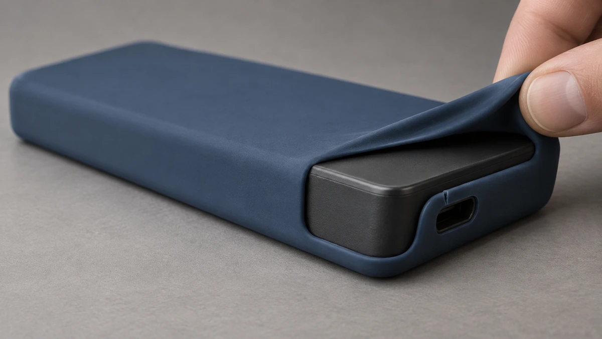
A short initial crack at the port cutout of a matte silicone protective sleeve during removal
Removal-related failure in a silicone protective sleeve: the crack often starts at the cutout corner repeatedly stretched during installation and removal.

A silicone protective sleeve may remain intact while fitted to a device, yet develop a crack at one corner of a charging-port or button cutout after it is removed for cleaning or servicing. Looking only at the final tear makes it easy to blame “silicone that is too soft” or “an edge that is too thin.”

Troubleshooting should begin at the moment the crack first appears. Did the first fine crack, referred to below as the “initial crack,” appear while the sleeve was being fitted, folded over the device edge, lifted at one corner, or pulled off? Which corner of the cutout cracked? In which direction was the sleeve being removed? Recording these three details helps determine whether the next step should be a structural change, an inspection of the mold joint and trimming position, or a review of the compound, cure condition, underfill, and surface damage.

Where Does the Force Concentrate During Removal?

This article deals with end users repeatedly installing and removing a protective sleeve. Demolding during production is a one-time removal from the tool. The force location, direction, and repetition differ between these two situations, so they should not share the same test method.

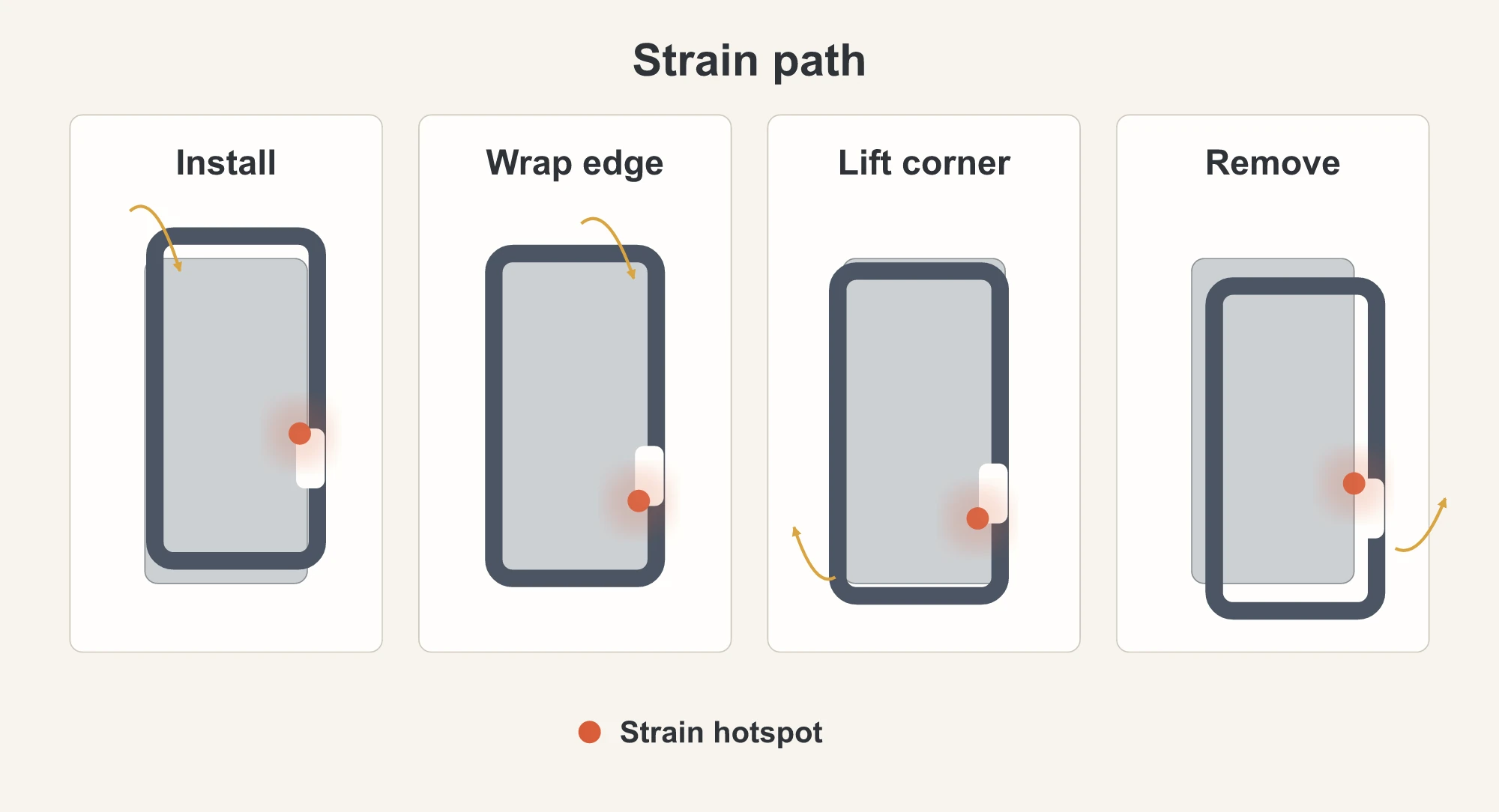
While the sleeve sits on the device, most of the shell simply maintains its wrapped shape. During installation or removal, the most heavily stressed area moves with the action. During fitting, the rim first stretches over a rigid device edge. As the rim is folded into place, one side of the silicone stretches and bends. During removal, a finger normally lifts one corner before the cutout passes over a port or button projection. The corner lifted first and the side pulled off first determine which cutout edge is stretched and bent first.

A cutout interrupts what would otherwise be a continuous shell wall. The sleeve as a whole may appear to deform only slightly, while a very small area around the cutout corner stretches much more than the rest. Engineers call this concentration of force within a small area a stress concentration. A fine crack can begin there, and each subsequent removal opens it a little farther until it becomes an obvious tear.

A test therefore cannot be described simply as “one installation and removal.” The device, fitting direction, order in which the rim is folded into place, first lift point, and removal motion must all be fixed. Otherwise, differences between two operators may reflect their handling rather than differences between samples.

Four installation and removal actions place the highest deformation at different cutout corners
End-use installation and removal: fitting, folding the rim, lifting an edge, and pulling the sleeve off load different cutout corners. This is not production demolding.

Why Adding Thickness May Still Fail

The silicone left between the cutout edge and the outer edge of the sleeve, or a nearby cavity, is the material that carries the pull. Production teams often call it the cutout-edge ligament or remaining wall. Its width matters, but it cannot be assessed alone. The corner shape, surrounding wall thickness, raised ribs that support the wall, and the main removal direction all interact.

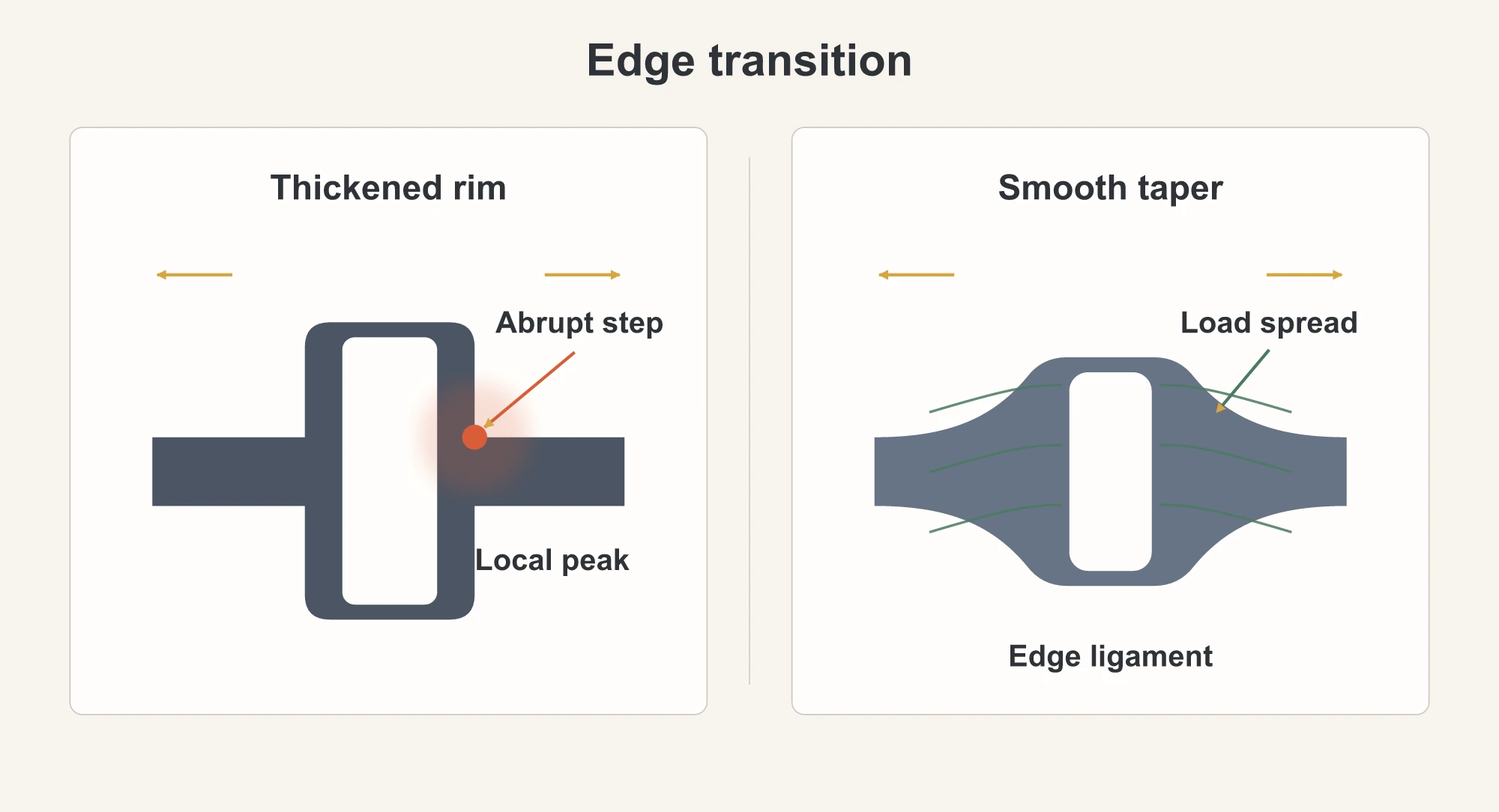
The reason is straightforward. A thin section stretches easily, while a suddenly thickened section is harder to deform. Thickening only the ring around the cutout may move the most heavily stretched area away from the cutout itself. The pull has not disappeared; it may instead concentrate where the thick section meets the thinner wall. Moving the crack does not mean the underlying problem has been solved.

Replacing a sharp corner with a radius is not enough either. A radius makes the transition smoother, but the pull may still concentrate within a small area if the wall beside it suddenly becomes thinner or if every removal pulls in that same direction. The entire path from the cutout corner into the surrounding wall must be examined: whether the corner transitions smoothly, whether enough silicone remains beside the cutout, whether the adjacent wall changes thickness abruptly or gradually, and whether a nearby support rib restrains the silicone around the corner from deforming with the rest of the wall.

There is no stand-alone radius or remaining-wall value that works for every product. A change in device dimensions, cutout geometry, compound, base wall thickness, or removal direction can change the suitable design. After the 3D structure is revised, the sample must be retested using the original removal motion to see whether the initial crack occurs later, moves to another location, or no longer appears.

Abrupt thickening concentrates deformation at a thickness step while a gradual transition spreads it
Cutout-edge thickness comparison: an abrupt increase can concentrate the pull where thick and thin walls meet. A gradual connection among the corner, remaining wall, and surrounding shell helps distribute the deformation. The drawing does not specify universal dimensions.

Start by Recording Where the Crack Begins

The final tear usually shows only where the part ultimately failed. Finding the origin requires recording what was happening when the first crack appeared. Before testing, assign fixed names to the four cutout corners, such as upper left, upper right, lower left, and lower right when the port faces upward. Photograph the sample from the same angle after each predetermined group of installation-removal cycles. The number of cycles in each group should reflect the product’s expected removal frequency and the required inspection interval. Also define in writing what crack size and visibility under specified lighting count as an “initial crack,” so every operator records the result from the same angle and to the same criterion.

Once the initial-crack location is known, compare three groups of information:

  • Product structure: the cutout corners, remaining edge material, wall-thickness transitions, nearby support ribs, and the main pulling direction during removal.
  • Manufacturing locations: the parting line left where the two mold halves meet, excess thin material at the joint (flash), and the trimming position.
  • Samples from the same batch: the silicone compound, the conditions used to heat and set the silicone in the mold (vulcanization or curing), and whether other samples develop their initial crack in the same location.

If cracks repeatedly appear at the same cutout corner, inspect the removal direction and the structure at that location first. If different samples crack at different locations, then review the compound, whether curing was complete, and the overall molding condition. Even when the initial crack coincides with a parting line or trimming position, this shows only that manufacturing may have left minor damage there; it does not establish the root cause by itself.

A real protective sleeve normally fits the device in only one orientation, so it should not be rotated merely for testing. A simple comparison is to keep the assembly orientation, order of folding the rim, and removal motion unchanged while changing only the point where the finger first lifts the sleeve. Then observe whether the initial crack moves with that lift point.

Changing the sample orientation is valid only when the part is symmetrical from left to right or top to bottom and still fits the device correctly after it is rotated.

Do not rush to a conclusion when reviewing the results. If the crack moves with the lift point, the removal action probably has the greater influence. If the same cutout corner cracks regardless of where removal starts, inspect the structure and manufacturing condition at that point first. If the crack location is inconsistent, first confirm that the sample batch and operating method are consistent. This comparison only narrows the investigation. Confirmation still requires a same-batch, same-structure control sample without visible trimming damage, tested with the same motion.

In our diseño de productos de siliconayFunda de silicona development work at YueHou, we review the 3D product structure, mold-joint position, condition of the molded samples, and actual installation-removal results together before deciding what to change next. The next sample round should not combine a new compound, a thicker cutout edge, and a revised radius. Change one item first and repeat the original removal test so the effect of that change can be identified.

Why a Material Report Cannot Replace Product Testing

A material report may show that hardness or tear strength meets the purchasing requirement even though the finished part still tears at a cutout. There is no contradiction. A hardness test, a material tear test, repeated flexing of a specimen with a small starter cut, and repeated removal of the finished product answer four different questions. ASTM is the abbreviation for ASTM International, formerly the American Society for Testing and Materials; D2240, D624, and D813 identify three separate standards.

Check or TestWhat It Can AnswerWhat It Cannot AnswerHow to Use the Result
ASTM D2240 Shore A hardnessUses a specified indenter geometry to compare how soft or hard a material is; useful for batch-to-batch checks.Does not show how readily a cutout edge will tear or how many installation-removal cycles a product will withstand.Use it for incoming-material and batch control, then evaluate tear behavior and finished-product performance separately.
ASTM D624 tear strengthCompares the tear resistance of compounds using specified specimen geometries and loading procedures.ASTM notes that specimen results may not correlate directly with service performance in the finished product.Use it to screen compounds, not as a substitute for testing the actual cutout geometry.
ASTM D813 cut growth under flexingIntroduces a small puncture into a rubber specimen, flexes it repeatedly, and observes how the crack grows.It is not a dedicated test for removing silicone protective sleeves and does not reproduce the device shape or removal sequence.Use it to understand whether an existing small cut is likely to propagate, then confirm the result on the finished product.
Repeated installation and removal using a fixed motionShows where a specific combination of device, cutout geometry, compound, and removal direction first cracks and how that crack grows.Results cannot be compared when operators use different motions, and they do not represent a universal service life for every protective sleeve.Fix the removal motion, camera angle, definitions of initial crack and final failure, and then set the cycle requirement for the product.

The test record should separate “initial crack” from “final failure.” An initial crack may be a visible fine crack defined before the test. Final failure may mean that the crack passes through the wall, the cutout deforms and no longer aligns with the port or button, or the sleeve can no longer be fitted properly. The product team must agree in advance on the point at which the part is no longer usable; in engineering testing, this common decision rule is called the “failure criterion.” Inspecting only for a large tear at the end of a test misses when the crack began and whether its growth accelerated, making it difficult to judge what a design revision actually improved.

A finished-product removal test should not record only a final cycle count. Inspect the cutout edge for small damage before the test. During the test, record the motion and location associated with the first crack, then observe how the crack grows. If different revisions must also be compared for ease of installation and removal, first standardize the operator, lift point, and rating scale. If a numerical force is required, define a separate force-measurement method. Material reports are useful for initial compound screening, while finished-product tests reveal where the real product begins to fail; one cannot replace the other.

Conclusión

When a silicone protective sleeve tears at a cutout, first identify the removal action and cutout corner associated with the initial crack. Then inspect the remaining material beside the cutout, corner radius, wall-thickness transition, parting line, and trimming position. Material-specimen data can help screen compounds, but it cannot replace repeated installation-removal testing on the actual product. Change one item at a time and repeat the same motion to determine whether the next revision should address the structure, manufacturing location, compound formulation, or curing condition.

EspañolEspañolEnglish (US)English (US)DeutschDeutschالعربيةالعربية
Scroll al inicio